
Much of the lighting for both commercial and residential applications is being upgraded to light-emitting diodes (LED). The advantages of LED luminaires are numerous: they are fully RoHS compliant and provide up to 85% energy savings; they can generate as much as 100 000 hours of light and are one of the most environmentally friendly and reliable solutions for outdoor lighting applications.
Although the LEDs themselves can last for more than 20 years, this service life only provides added value to the lighting system if the electronic components and power supply drivers are as reliable as the LEDs. Also, LEDs do not usually fail catastrophically; the lumen output gradually decreases until the LEDs are classified as having failed.
All of the components in the luminaire must be able to withstand the harsh conditions of the environments in which they are installed, whether in the tropical climates of the Caribbean or the extreme cold of Alaska.
Challenges of harsh environments
According to a study performed by RTI International, the leading causes of solid-state LED luminaire failures are issues with drivers, such as capacitor and interconnect failure, electrical stress, and ingress of moisture or other chemicals. Traditional power supply drivers come with a five-year warranty, and tests have shown that these power supplies have a high failure rate. These issues are often caused by seals, joints and connection points being compromised by challenging environmental conditions.
Most engineers protect the drivers and electronics by enhancing the durability of the luminaire housing in one of three ways – integrating more rugged O-rings or gaskets to improve seals; increasing the thickness of the enclosure’s walls to minimise movement of the housing around the seal; or installing additional bolts around the O-rings or gaskets to maintain a more durable seal.
However, even with these added features, the seals can begin to fail and become a leak point, providing a path for water to enter and eventually cause condensation on the lens and reflectors. These failures occur because sealing the device prevents its ability to handle pressure fluctuations, both positive pressure and negative pressure (i.e., vacuum).
As these pressure fluctuations occur, they put significant stress on seals and other connection points, which in turn compromises their effectiveness. Over time, the frequent expanding and contracting of the seals causes their weakest point to begin to allow water and contaminants to enter the housing, which can lead to corrosion, shorts and potential failure of the electronics.
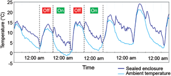
Temperature changes – whether external, internal or both – are one of the most common causes of pressure differentials. External temperature changes can be dramatic (e.g., a sudden thunderstorm on a hot summer day) or more gradual over the course of different seasons. Daily temperatures can drop as much as 10 to 20 degrees Centigrade from day to night, and seasonal temperatures can differ 40 degrees or more between summer and winter.
As the temperature rises, the air inside the luminaire expands, putting positive pressure on the seals, joints and connection points. As the temperature drops, the internal air compresses and creates a vacuum, again putting pressure on the seals. A 30°C change in temperature would create approximately 10% of volumetric flow of air in or out of the luminaire.
A quick drop in the outside temperature can create a vacuum of 0,5 psi or greater inside the enclosure. When a vacuum occurs, water and contaminants can enter the housing. In mild cases, corrosion is accelerated and in severe cases, catastrophic failure could occur. The corrosion can shorten the life of the luminaire by damaging wiring, leads and other electronics contained within the power supply driver and the LEDs.
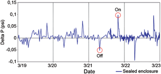
As a luminaire turns on and off, the changes in temperatures result in sudden pressure differentials (Figure 2). The housing tries to relieve the pressure by drawing air inside, which increases stress on the seals (a process sometimes referred to as pressure equalisation).
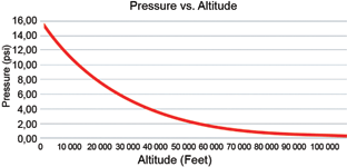
Altitude changes are another common cause of pressure build-up. Although luminaires are usually stationary once installed, altitude issues occur as the luminaires are shipped from the manufacturing facility to the installation site. Because most shipping containers on cargo plane are not pressurised, luminaires can be exposed to significant pressure differentials during take-off and landing, decreasing from almost 15 psi (1034 mbar) when on the ground to about 3 psi (137,9 mbar) at an altitude of 40 000 feet (Figure 3).
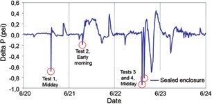
A third cause of pressure differentials is the thermal shock experienced when the luminaire is exposed to rain, snow or washing cycles. Figure 4 shows the impact on a luminaire’s internal pressure from a water spray using an IEC 60529 standard IPX5 nozzle at a distance of approximately 3 m for three minutes, with a tap water flow of 21 litres/minute. Rapid recovery of pressure indicates the failure of a gasket to hold the vacuum, drawing water along with air in at the leak path(s).
Condensation
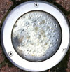
In addition to the potential damage to electronics if water and contaminants enter the luminaire, moisture vapour from the water can cause condensation on lenses and reflectors, decreasing light efficiency and the aesthetic quality of the luminaire (Figure 5).
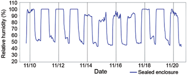
The relative humidity inside the luminaire determines the potential for condensation occurring on the lenses and reflectors. When the relative humidity inside the luminaire reaches 100%, condensation occurs. Once this happens, the condensation will remain unless there is a path for the moisture vapour to escape. Sealed enclosures do not provide this path; therefore, once condensation occurs, it will remain on the lenses and reflectors for extended periods (Figure 6).
Preventing pressure differentials
The challenge in maintaining constant pressure inside a luminaire is to allow air to flow freely in and out of the luminaire while blocking water and contaminants. Drilling a hole in the housing or creating a hole with a torturous path definitely addresses the pressure differential issue; however, this open system concept allows contaminants, including dust, dirt, water and even insects, to enter the enclosure and compromise the electronics.
Many engineers consider hermetic seals or potting compound to be the best way to protect electronics. However, hermetically sealing the device requires the use of non-permeable materials – which means no plastic – and the housing is welded shut. This option is unrealistic for most luminaires because the enclosures would be too heavy, not serviceable and very expensive.
Like hermetic seals, potting compound eliminates the ability to service the electronics, is expensive and heavy, and requires specialised equipment in the manufacturing process.
Installing a felt element, sintered vent or mechanical valve is another alternative. The felt element and sintered vent address the pressure differentials, but like tortuous paths, they allow water and contaminants to enter and clog the air path. And the mechanical valve is a one-way solution – allowing air to escape only if internal pressure increases to a certain point, but remaining closed if a vacuum occurs.
Finally, a vent made of expanded polytetrafluoroethylene (ePTFE) – a two-way breathable membrane – continuously equalises pressure inside the luminaire housing while maintaining an environmental seal. Expanded PTFE is a unique, microporous membrane that is inherently waterproof and chemically inert, and can be coated to provide oleophobicity. Its node-and-fibril microstructure is open enough to allow gas molecules and vapour to pass through it easily, but the openings are so small that liquid and other particulates are repelled.
Venting to improve reliability and durability
Equalising pressure using an ePTFE vent reduces the potential for seals to fail and for moisture vapour to condense on the lenses and reflectors. W. L. Gore & Associates has performed extended life testing on two commercially available LED luminaires to evaluate the effect of using ePTFE venting products as a solution to improve reliability and durability by relieving pressure.
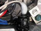
The vent is integrated into the power supply chamber of the luminaire. It is extremely difficult to leak-proof any entry point of an enclosure, because the gasket elastomer and the wire gland relax over time (Figure 7). A sealed housing may pass ingress testing at the factory but fail rapidly in real life when challenged by a wide range of temperatures.
Depending on the quality of the seal, negative 34 mbar (approximately 0,5 psi) is commonly accepted as the point at which a vacuum can cause a leak in a sealed enclosure. Although the on/off cycle of a luminaire causes temperatures to rise and fall in both a vented and a sealed enclosure, the amount of pressure placed on the seals and joints is significantly different (Figure 8).
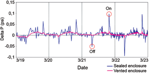
The testing indicated that pressure in the sealed luminaire spiked as much as 0,09 psi when the light was turned on and dipped approximately -0,1 psi when turned off. However, the vented luminaire showed a change of only ±0,01 psi.
Comparing the relative humidity inside the sealed and vented luminaires after an IPX5 water ingress test demonstrates the significance of pressure differentials. Following the water spray test performed by Gore, the relative humidity in a sealed luminaire remained significantly higher than that in an identical luminaire that was vented (Figure 9).
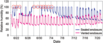
Over the course of 10 days, the relative humidity of the sealed luminaire almost always remained at 100%, which indicated condensation inside the luminaire caused by water entering during the test. Although the relative humidity in the vented luminaire rose after the shock test, it decreased as the moisture vapour escaped from the enclosure and there was no evidence of condensation.
Conclusion
Pressure differentials compromise the housing seals, joints and other connection points in LED luminaire systems. Leaving these pressure fluctuations unchecked can reduce long-term performance of the power supply drivers and other electronics. They also lead to condensation on lenses and reflectors that can decrease light efficiency and the aesthetic quality of the luminaire.
As demonstrated through the real-life IPX5 testing done by Gore, integrating an ePTFE vent into the luminaire’s housing equalises pressure by allowing continuous airflow in both directions. This two-way airflow prevented water from entering as the pressure changed inside or outside the enclosure. Also, the vent reduced condensation events inside the luminaire because moisture vapour was able to escape before condensing.
For more information visit www.gore.com/protectivevents
© Technews Publishing (Pty) Ltd | All Rights Reserved