As the demand for electronic components continues to grow in more diverse and complex embedded systems, it becomes crucial to protect sensitive applications against over-current conditions.
Reliable circuit protection is a fundamental design consideration for cost-effective, long-lasting products. Each time a user plugs in, operates or leaves devices unattended, it is essential that there is a mechanism in place to ensure that no above-range current damages the very circuits that allow the device to work.
Since most applications will not be accessible conveniently for replacement, such as with a conventional fuse or household circuit breaker, the concept of a resettable fuse has been adopted nearly universally. Some interface standards even require resettable over-current protection, recognising and reminding designers in advance about the importance of robust circuit protection. The capability of delivering a smaller, faster and lighter product than the competition truly begins at the component level, where parts are pushing the envelope with regard to minimal board space requirements and versatile use environments.
Over-current and over-temperature conditions are a reality that can lead to costly field failures. Ignoring the need for over-current protection is not an option, so the question remains as to how to incorporate this feature without sacrificing the design constraints or objectives. This article details some of the latest advances in circuit protection technology integrated into Bourns’ line of resettable Multifuse products that now incorporate a new space-saving freeXpansion manufacturing process.
From the inside out, Multifuse devices are specifically designed to shield a wide range of applications against the potentially destructive effects of these conditions. Once system requirements are defined and circuit analysis has determined the operating parameters, as illustrated by example in this article, it is straightforward to select the component appropriate for a given design. A wide range of speed, voltage and current limits among the Multifuse devices and specific series for products like USB, which by standard requires resettable over-current protection, ensures that the ideal component can be incorporated in a given design without sacrificing board real estate.
Inside Multifuse resettable fuse technology
Multifuse devices are manufactured from a mixture of polymer, carbon and other proprietary materials placed in a mould and then ‘punched’ out of the mould. The characteristics of a given Multifuse device can be customised by adjusting the quantity of each ingredient within the composition or by changing the area of the cutout. Conductive carbon chains embedded in plastic in the Multifuse design create an environment of low impedance – 3 mΩ to 8 Ω. The proximity of the carbon chains in this crystalline structure provides for easy current flow and the component offers low resistance at operating current.
As is common to many materials, these resettable fuses exhibit a positive temperature coefficient (PTC) effect when heated. As the PTC increases due to current or ambient temperature, the material expands. This expansion increases the impedance from low to high, effectively creating an open circuit with some leakage current.
Characteristic of resettable fuses such as Multifuse devices is the exponential rather than linear increase in resistance with rising temperature. The black carbon impregnated in the plastic becomes isolated as temperature increases, turning the crystalline polymer amorphous instead to prevent current flow and thus increasing the resistance at a rate of I²R. In fact, resistance increases by two orders of magnitude when the circuit trips. It is this transformation of the material from low resistance to high resistance when a Multifuse device trips, that allows this resettable fuse to protect the load from over-current. Once the current is removed, the material will cool and return to its highly conductive crystalline state.
It is important for designers to understand that after the device has tripped and current is removed, the Multifuse device must be power cycled to reset. If the power is left on following a trip event, the Multifuse device does not reset on its own. After an extended period in tripped mode, the component continues generating heat in the tripped state, causing a very high level of resistance that will prevent the device from resetting even after power has been cycled. The proper method for resetting a Multifuse device is to cycle power to the device typically within one second. When the power source is removed, the device simply resets itself.
What makes Multifuse devices unique
Bourns has developed a new manufacturing process technology called freeXpansion that is being rolled out across its surface mount polymer PTC Multifuse product line. The expansion of materials during a trip and the contraction of materials upon reset occurs without any mechanical restrictions in Multifuse devices with freeXpansion technology. Enabling smaller surface mount package sizes, this technology made the launch of the new 0603 size family possible. Additional freeXpansion benefits include the ability for Multifuse devices to handle larger currents and voltages with improved resistance stability.
Several series of Multifuse devices take advantage of this technology to meet the voltage and current requirements delivering reliable over-current and over-temperature protection for a wide range of consumer electronics, automotive electronics, USB interface and video interface applications. One example of a targeted application is USB 3.0, which was released in November 2008 and specifies higher operating currents than its USB 2.0 predecessor.
Selecting the appropriate Multifuse device
The operational life of a Multifuse device depends on the surge, duration and spike of the current to which it is exposed in a given system. Multifuse devices have been designed and tested to meet industry standards for the most demanding environments and applications, making the selection of the appropriate device simple from series to specific component. Only the tripping point, voltage requirements and package size are necessary considerations for Multifuse device selection.
Because a larger chip package results in larger thermal mass, the material heats slower than a smaller package. A smaller package trips faster, although it will have higher resistance for the same holding current. Multifuse devices are able to trip in a fraction of a second, and the proper Multifuse component can be chosen to protect the load for a given design based on the maximum allowable trip time. The 0603 package provides a clear advantage for space-constrained applications where reducing board space is a top priority.
Given the expansion of electronic devices and the increase in human interface with those electronics, there is more need for creative over-current solutions to ensure efficient use of all system resources. Several examples will illustrate the design and selection process when using Bourns Multifuse devices for over-current protection.
General calculations
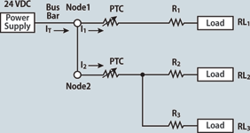
When numerous loads are sharing the same power supply, it can be advantageous to allow each load to operate independently or in subsets, instead of hinging the operation of every load on the system current condition. It is possible to instantiate multiple PTCs for multiple nodes sharing a power supply, as shown in Figure 1. In this case, Ohm’s law will calculate simply the current condition for each node and therefore determine which PTC to choose based on the current in each node.

For the given example, the power supply is 24 V and resistor values are R1=2 Ω, RL1=6 Ω, R2=5 Ω, RL2=19 Ω, R3=10 Ω, RL3=14 Ω. Resistance at Node 1 is given by the series resistance calculation R1+RL1=8 Ω. Resistance at Node 2 is given by the parallel resistance calculation (1/((1/(R2+RL2))+(1/(R3+RL3))))=12 Ω. The current IT going into the nodes is equal to the sum of the current going into the nodes and is given by IT=I1+I2. Using V=IR to calculate the current I1=V/8 Ω = 3 A. I2=V/12 Ω = 2 A. The total current IT=5 A.
Based on these results, the holding current of the PPTC chosen for Node 1 shall be 3 A or greater and the PPTC chosen for Node 2 shall be 2 A or greater. For each selection, it is important to verify that Imax is at least 5 A to meet the current of the system. If the PTC on either of the branches trips then the current flowing in the system is reduced to the current of the remaining operating branch. Had there instead been a single PTC placed between the power supply and Node 1, the selected PTC would require a holding current of IT=5 A and Imax > 5 A. Given that the power supply operates at 24 V nominally, selecting a component with margin is advisable. As such, the appropriate choices would be a 30 V or greater part with Imax > 5 A for the former case and a 30 V or greater part with Ihold > 5 A for the latter case.
There are several Multifuse product lines geared to meet the demands of a specific application. Power-over-Ethernet (PoE), USB and Firewire are three such applications. Selection of the component is quite simple based on the current seen at the various ports in the system.
Power-over-Ethernet
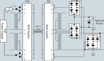
For Power-over-Etherent (PoE) over-current protection, one Multifuse device is specifically designed to meet the 350 mA interface at up to 57 V. Figure 2 illustrates how one PTC placed at the power supply provides over-current protection in a circuit laden with transformers. This over-current protection is necessary only at the source.

USB
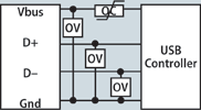
USB is a four-wire interface with a pair of data lines, power and ground, and it is a requirement that a resettable circuit is used for over-current protection. For any design using a USB interface it is only essential to provide over-current protection on the power line, and all three power and data lines will utilise over-voltage protection, as illustrated in Figure 3.

As seen in the general USB interface example, it is possible to use one PTC device for several USB controllers or one PTC device per USB controller. This decision is made based on the resistance and current in each load and the board space available. An additional consideration when choosing a Multifuse device for a USB application is maintaining a low resistance, namely under 700 m with a voltage drop below 350 mV. With the introduction of USB 3.0, current requirements are greater, which may lead to designing a dedicated PTC for each line.
Since the USB standard operating voltage is always 5 V, the Multifuse device’s minimum voltage of 6 V provides at least a 20% margin over the USB required voltage for an additional cushion of protection. The short circuit current as defined by the USB specification is 5 A. After 60 seconds of operation, a maximum operating current of 5 A is allowed for a USB port. However, the normal operating current for low-power ports is 100 mA and for high power ports only 500 mA, both of which are far beneath the 5 A short circuit level.
A wide range of Multifuse parts are available for USB designs at a 6 V rating. Once the current and trip time for a device are determined, it is simple to select the appropriate part. For USB protection, Multifuse resettable fuses are represented by two product lines which differ in their current handling capabilities.
Firewire
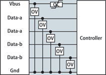
Firewire, also known as IEEE-1394, is similar to USB in its design although resettable fuses are not required. All power sources of the interface require over-current protection per the IEEE-1394 standard. The example in Figure 4 illustrates over-current protection on the voltage line and over-voltage protection on the voltage and data lines. As with USB, the Multifuse device is capable of handling over-current for one controller or multiple controllers based on the needs of the system and the number of loads. Typically up to four controllers can share a single Multifuse device. There are four power levels for devices in the Firewire standard, and the maximum of each is 30 V, which is significantly higher than that of USB at 5 V. Current ranges from 100 mA to 1,5 A based on 15 W, 30 W, 45 W and 3 W maximum power for the four respective power levels.

© Technews Publishing (Pty) Ltd | All Rights Reserved