


In an age of increasing data acquisition and electrification in almost all areas, the demand for quality and reliability of electronic PCBAs is constantly rising. Sufficient surface cleanliness is essential to ensure their long-term functionality. Failures due to contamination can cause considerable and often incalculable additional costs. Such impurities arise, for example, during production or as a result of sub-optimal cleaning processes.
In an age of increasing data acquisition and electrification in almost all areas, the demand for quality and reliability of electronic PCBAs is constantly rising. Sufficient surface cleanliness is essential to ensure their long-term functionality. Failures due to contamination can cause considerable and often incalculable additional costs. Such impurities arise, for example, during production or as a result of sub-optimal cleaning processes.
These instances of contamination often manifest themselves as undesirable surface phenomena, such as white spots. The first reactions are often a lack of understanding or, in the case of an implemented and previous cleaning process, the statement: “The cleaning medium is not working”. There are actually a number of factors that can cause such problems.
The following section presents common types of surface residues on PCBAs, analyses their possible causes, and suggests solutions.
1. Production-related: residues after the soldering process
Process-related residues often occur on printed circuit boards after a soldering process. Particularly noteworthy are flux residues and solder beads, which occur as typical contaminants.
1.1 Source of contamination: flux residues
Fluxes are used in a wide range of applications in electronics production and, depending on the type of production, can either be applied directly to the PCBA (THT production) or used as a component of a solder paste (mainly SMT production). Fluxes are necessary, for example, to optimise the rheological properties of the solder for processing. They play a key role in ensuring good wettability of the solder joint with the solder wire, the solder paste and the liquid solder.
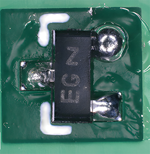
During a soldering process, however, the flux used may not evaporate completely, resulting in flux residues on the circuit board. Visually, these can usually be recognised as a translucent film around the area of the solder joint, as shown in Figure 2.
In addition to incomplete evaporation of the flux, other influencing factors can be responsible for visible residues on printed circuit boards. These factors include:
• The type of flux (water-soluble/non-water-soluble).
• The soldering technology used (manual/SMT/THT).
• The soldering time.
• The temperature.
• Soldering under inert gas or air.
Depending on these variables, a yellowish/orange/brownish discolouration may occur with different levels of stress. This discolouration indicates that the flux residues are more strongly burnt in.
Flux residues are therefore not only a visual blemish, but also harbour a considerable risk of quality degradation and failure mechanisms, such as electrochemical migration or poor adhesion of coatings. Flux residues also have hygroscopic properties, that is, they attract moisture from the air and can carry moisture into subsequent production steps. Removal of these residues is therefore essential, and a suitable cleaning process can remove these effectively. In addition, by adjusting the soldering process parameters, depending on the requirements of the end application, a reduction or, in individual cases, a complete elimination of the flux can be achieved.
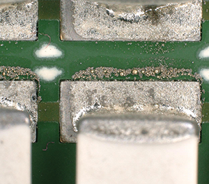
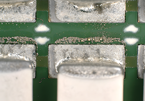
1.2 Solder beads: risk of short circuit on printed circuit boards
In addition to the classic flux residues, so-called solder beads can also remain on the surface after a soldering process, in particular on the solder resist of the PCBA (see Figure 3), and later become mobile. Depending on their size, frequency, and distribution, these can create unexpected connections as percolation paths, which can lead to short circuits.
Thorough removal of all solder beads is essential to counteract the risk of failure due to short circuits. Cleaning can be a possible solution here. However, this depends on whether the solder bead adheres to the surface due to flux or whether the solder bead is baked into the PCBA surface.
If there is adhesion due to the flux, a suitable cleaning process can remove the flux, which automatically leads to the solder beads coming off. The solder beads are entrained with the cleaning agent or rinsing medium and collected in the filter system of the cleaning system.
Furthermore, regular cleaning of the stencils required for printing solder pastes can help to avoid solder beads on PCBA surfaces. This is because as the service life of stencils increases, solder paste material also collects in undesirable places and can get onto the solder resist. This effect is caused by the clogging of equipment, the loss of edge stability of the paste and the introduction of dried solder paste residues. If solder beads are already burnt onto the PCBA, it is advisable not only to adjust the soldering parameters, but also to clean the stencil or increase the cleaning frequency. It is not possible to clean the burnt-in solder beads afterwards.
2 Cleaning process: related residues
If a cleaning step is implemented in a production process, there are a few aspects to consider to avoid undesirable phenomena in the form of marks on the PCBAs after cleaning. The selection of the right cleaning chemicals plays a major role. Due to the enormous variety of solder pastes on the market, it is necessary to adapt the chemicals involved to the corresponding flux system and other requirements.
Typical residues that can occur after a cleaning process that has not been optimised are listed below.
2.1 Dissolved flux residues
If the cleaning chemicals are not selected appropriately or the cleaning time/mechanics and/or temperature are not sufficient, the flux residues may not be completely removed. A typical indication of this is the flaky arrangement of the flux residues around the solder joint.
2.2 Rinsing water
Another important aspect of cleaning processes is the purity of the rinsing water. To achieve the best possible cleaning result, it is important not only to remove the flux residues, but also to ensure that the cleaning medium is rinsed off sufficiently. It is generally recommended to use demineralised water with an electrical conductivity of less than 10 μS/cm, as this water contains only very small traces of dissolved salts and minerals, which prevents them from settling on the PCBA surface during drying. The electrical conductivity of the rinsing water in a system is therefore a good physical measure for monitoring the ionic purity of the rinsing water during the cleaning process.
If the rinsing water is not of sufficient quality, white residues may remain on the circuit board. An initial indication of rinsing marks is if the marks are not directly next to components and solder joints, but on PCBA areas where flux has not been applied. These marks are most likely caused by dried drops of rinsing water with too much residue. Residues of the cleaning medium that have not been washed off are often referred to as rinsing marks.
2.3 Soldermask
Another phenomenon that can lead to whitish marks after cleaning is due to the quality of the solder mask. If this is not fully cured, cleaning agents or rinsing water can become embedded in the solder resist material and subsequently condense. Areas are created, usually around the solder joints, which visually resemble a whitish haze. This is due to the fact that solder joints experience the most thermal stress during the soldering process and the solder resist can become porous in the vicinity. Hot air can be blown onto these points with a hot air gun to eliminate the milky area.
3 Changing solder pastes/components
In addition to these aspects relating to cleaning, changing solder pastes or components on the PCBAs should not be underestimated.
Materials such as solder pastes are subject to constant development and therefore bring ever newer advantages. This can be a reason for changing the pastes, even if the current process does not cause any problems. The focus is usually on soldering quality and suitable solderability. The established cleaning process is often not given enough attention, which makes it even more shocking when phenomena such as those mentioned above suddenly and unexpectedly occur.
The cleaning chemicals used are designed for the previously used flux system and cannot generally be used across a wide range of applications. The cleaning performance should therefore always be checked when changing soldering materials. When replacing components on a PCBA, colours may be washed out or even material incompatibility may occur, which can lead to chemical attack on the materials of a component.
Speak to a company that offers both expertise and options to analyse marks on the PCBA to determine the cause more precisely.
| Tel: | +27 11 726 6758 |
| Email: | [email protected] |
| www: | www.eispty.co.za |
| Articles: | More information and articles about Electronic Industry Supplies |


© Technews Publishing (Pty) Ltd | All Rights Reserved
 printer friendly version