


Phased array beamforming has been used in radar and communication systems since the mid-20th century. In recent years, these systems have seen extensive adoption in areas such as 5G mobile communications, military and commercial radars, satellite communications, and automotive applications.
Phased array antennas (or beamforming antennas) have an electronically steerable radiation pattern, allowing a robust communication link to be established between two radios. Power from the transmitter can be directed toward the intended receiver, and the receiving antenna can be aimed at the transmitter. In addition, nulls in the receiver’s antenna pattern can be placed to reject interfering signals, and a link can be maintained between two radios that are moving with respect to one another. Phased arrays vary widely in complexity, from a few elements in a simple linear array to thousands of elements in planar, cylindrical, conical, and other shaped arrays.
Phased arrays have a steep learning curve, spanning multiple technological and engineering disciplines including microwave RF electronics, continuous and discrete-time signal processing, embedded systems, analogue-to-digital and digital-to-analogue converters, digital design, and computer networking. Commercial phased array systems are typically expensive and built for a single application and are, therefore, not conducive to exploration of basic concepts.
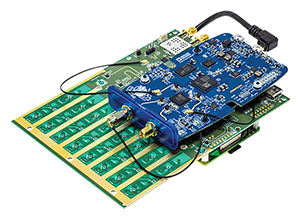
This circuit developed is a low cost, simplified phased array beamforming demonstration platform that offers a hands-on approach to learning about the principles and applications of phased array antennas. The complete system provides an ideal tool for proof of concept or debugging of more complex systems. It offers the opportunity to explore and understand advanced topics such as beamforming, beam steering, antenna impairments, frequency modulated continuous wave (FMCW) radar, and synthetic aperture imaging. The design consists of RF components, signal processing hardware, and contains an on-board 8-element linear array antenna that operates from 10,0 to 10,5 GHz (X band). This frequency range allows common low-cost motion sensor modules to be used as a microwave source.
The circuit is designed to mount directly on a Raspberry Pi, and uses the PlutoSDR low-cost software defined radio (SDR) module to digitise the intermediate frequency (IF) output. The software interface is through the Linux industrial input/output framework, providing a host of debug and development utilities, and cross-platform API with Python, GNURadio, and MATLAB support.
Application software can run either locally on the Raspberry Pi, or remotely via a wired or wireless network connection. The entire system is powered via a single 5 V, 3 A USB-C power adaptor.

Beamforming fundamentals
Phased array beamforming is a signal processing technique used in antenna arrays for radio communications, radar systems, and medical imaging. Beamforming provides many benefits – the antenna can be aimed directly at a target, which may be a transmitter, receiver, or object being tracked in the case of radar. The antenna pattern’s nulls can also be strategically placed to avoid interfering signals.
Forming a beam pattern involves the simultaneous transmission or reception of signals from multiple antennas. A phase shift with gain adjustment is applied to each channel. Thereafter, the individual channels are summed together in either the analogue or digital domain, or a hybrid of both. The phase shifters are adjusted to control the direction of the combined radio RF beam, allowing for real-time beam steering and reconfiguration, without physically moving the antennas. The main beam width and sidelobe suppression can be adjusted by adjusting the gain (or tapering) the array elements.
The CN0566 main board implements an eight-element phased array, down-converting mixers, local oscillator, and digital control circuitry. The CN0566 outputs are two IF signals at a nominal frequency of 2,2 GHz, that are digitised by a PlutoSDR module.
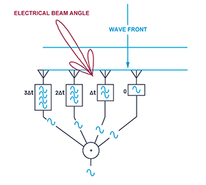
Figures 2 and 3 provide simple illustrations of a wavefront received by four antenna elements from two different directions. The electrical beam is steered 45º to the left, toward the desired transmitter, by inserting time delays in the receive paths, and then summing all four signals together.
In Figure 3, that time delay (configured for a 45° beam) matches the time difference of the wavefront striking each element. In this case, that applied delay causes the four signals to arrive in phase at the point of combination. This coherent combining results in a larger signal at the output of the combiner.
To continue reading visit https://bit.ly/458r5r6
| Tel: | +27 11 923 9600 |
| Email: | [email protected] |
| www: | www.altronarrow.com |
| Articles: | More information and articles about Altron Arrow |


© Technews Publishing (Pty) Ltd | All Rights Reserved
 printer friendly version