Control of switch mode power supplies (SMPSs) has traditionally been carried out with purely analog circuitry.
The advent of low-cost, high-performance digital signal controllers (DSCs) provides a practical route to realising the benefits of digital power supplies, in areas such as:
* Bill-of-materials (BOM) costs for digital vs. analog power supplies.
* Control flexibility and the ability to control advanced topologies.
* Implementation of added-value functions without adding to the cost.
Digital PSU cost savings
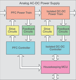
Figure 1 illustrates a high-level block diagram for a generic two-stage analog AC-DC power supply. Key functions include:
* Power train: semiconductor switches, inductors, capacitors and power transformers.
* Power switch drive: gate drivers and supporting circuitry.
* Feedback: sensors, amplifiers and resistor networks.
* Control: dedicated controllers for each power stage.
* Housekeeping: a dedicated microcontroller and supporting circuitry for sequencing, monitoring and communications.

For the purpose of comparison, a two-stage power supply is considered. The front end converter is a boost power factor correction (PFC) circuit, while the second stage is a DC-DC phase-shifted full bridge converter.
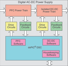
Some of these elements, for example the power train, drive and feedback circuits, are essentially identical in an analog or a digital power supply. Figure 2 illustrates the corresponding digital power supply for the same example. For the digital version of this power supply, the functions of both the dedicated analog controller, and housekeeping MCU can be combined in a single dsPIC DSC.

Figures 1 and 2 show only the major differences from a high-level perspective; however, all supporting circuitry must also be included in the comparison. Each stage of the analog supply typically requires circuitry to provide auxiliary power, plus leading-edge blanking, oscillator, sequencing control, soft-start and compensation functions, all connected to a central controller.
A digital implementation will still need hardware for auxiliary-power circuitry, but each of the other functions listed above become software running on the central controller. Not only are fewer components required, but physical connections (PCB tracks) are also greatly reduced. Analysis of the bill of materials should consider the cost of this supporting circuitry, layout complexity and the size of the PCB. Some of the functions identified above may (in the analog implementation) require no more than a few passive components, while others have a higher cost (a separate MCU for housekeeping functions, for example).
Some may argue that a digital solution requires the use of dedicated MOSFET gate drivers, while an analog solution may provide the gate drivers on-chip. While this is true for low-power designs, most high-power analog designs will still need to use external gate drivers.
A detailed comparison of BOM costs will invariably show a significantly lower total for a digital supply over an analog design with comparable features. A simple summation of component costs is only part of the story: there are many consequent savings that follow from digital power supplies offering simpler layout, smaller PCBs, reduced PCB fabrication and assembly costs, and improved quality and reliability.
Efficiency optimisations
In recent years, continuous improvement in power transistor performance, and use of novel topologies, have contributed to significant improvements in power supply efficiency. However, quoted maximum efficiency figures most often apply only at certain specified operating conditions (peak efficiency may be specified at half-load or at high line voltages). Digital power supplies offer added versatility to optimise the efficiency at multiple operating points.
For the PFC boost converter, switching losses can be reduced at lighter loads by operating the converter at a lower switching frequency. Due to the lighter load, the magnetic components will still perform adequately at the lower switching frequencies. If an interleaved PFC converter is implemented, one phase can be turned off at light loads.
Similarly, for a phase-shifted full-bridge converter, extra switching losses can be eliminated at light loads by turning off switching of the synchronous MOSFETs and using the devices’ body diodes instead.
Another example occurs in a buck converter application. Synchronous buck converters are typically preferred for high current outputs. However, using a synchronous MOSFET leads to circulating currents at light loads, which in turn causes higher losses. Therefore, the synchronous/free-wheeling MOSFET in a buck converter can be disabled when the converter operates in discontinuous-current mode.
These techniques supplement the efficiency gains obtained through use of advanced topologies such as resonant and quasi-resonant converters. Digital control fully supports these advanced topologies, including phase-shifted full-bridge and LLC-resonant converters, to achieve very high efficiency and power density. As a result, digital control provides many options to optimise the efficiency of power supplies over the entire range of operation.
This http://www.dataweek.co.za/News.ASPx?pklNewsID=40252&pklIssueId=895&pklIssueTypeId=5&LIU=15article will be continued in the next edition of Dataweek.
| Email: | [email protected] |
| www: | |
| Articles: | More information and articles about Tempe Technologies |

© Technews Publishing (Pty) Ltd | All Rights Reserved