An antenna is an electrical component that is needed to transmit and receive electromagnetic energy from the space surrounding it in order to establish a wireless connection between two or more devices. The variety of devices using wireless communication is enormous, for example mobile phones, base stations, and wireless local area network connections (WLAN).
Because of the wide variety of antenna-using devices, multiple types of antennas are needed and available. The antenna’s performance, in general, is characterised by some basic terms, such as antenna efficiency and gain. In this article, these basic antenna characteristics and their definitions are introduced.
Antennas have many different attributes and the type of antenna that is needed depends on many characteristics. One of the main attributes is the operating frequency or frequencies. Some machine-to-machine (M2M) antennas might work on only one ISM band, while modern mobile phones or laptop dongles might have almost 10 operating bands that all need to be implemented in one device. The operating frequency selection for certain antennas in part determines the material that can be used to produce the antenna. Materials include flex, ceramic, steel plate, FR-4 or some wire material.
The type of antenna element is another important attribute. To implement several frequency bands in one antenna element, planar inverted-F antennas (PIFAs) are commonly used, but monopoles with parasitic elements are well known, too. These basic antenna structures, together with traditional inverted-F antennas (IFAs), can also be used in ceramic antennas. With newer wireless technologies, the selection of operating frequencies is widening and allocated frequency bands are getting lower, which creates demand for more antenna area and volume on the device at a time when consumers want things smaller, especially with handheld and portable devices. It is the antenna that takes the brunt of the burden for size constraint. Therefore, physical size has taken on increased importance in antenna design.
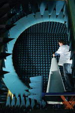
Other attributes involve antenna performance, which is evaluated in terms of resonance bandwidth. The antenna naturally needs to cover all intended frequency ranges with low enough antenna feed port impedance matching and high enough radiation performance. Although resonance bandwidth can be initially verified with a network analyser (impedance matching), a more meaningful evaluation is done in an anechoic chamber using a passive or active device to get an accurate antenna efficiency measurement.

Passive antenna measurements are executed for passive devices during the R&D process to give some guidelines for the progress of the antenna’s development. It is very useful information during the antenna R&D process because it guides the designers towards a final antenna solution. A passive device can be some kind of a mock-up model and is not required to be operational since the idea in this is to compare different antenna solutions to each other.
The final device performance evaluation, however, needs to be made with a fully functional active device. This reveals if there is some interference caused by the device itself on the antenna’s operation. Any problems naturally need to be eliminated. In active measurements, one measures the total radiated power (TRP) and total isotropic sensitivity (TIS) of the device. These figures combine the antenna performance with the device’s radio capability.
The TRP value indicates the power level that the device’s radio can deliver through the antenna to the surrounding space, while TIS indicates the radio’s capability to sense incoming signals with a low power level. These two important parameters are specified by mobile operators, and their requirements have to be fulfilled prior to the designed device being brought to market. Making sure that the antenna performs with great enough efficiency throughout the entire operating band or bands with an active device, ensures that the antenna and the device’s entire radio is of good quality.
Some additional antenna evaluation metrics, such as standing wave ratio (SWR) value, isolation between antenna elements, and antenna impedance matching to feed line, are characteristics that are verified with a network analyser. In some cases, gain (directivity) and antenna polarisation are important attributes. Metrics for these can be determined in an anechoic chamber.

For multiradio devices, the isolation between antenna elements plays a very important role, as isolation between antennas should be kept as high as possible. In modern 4G applications that might include multiple antennas operating on the same frequency ranges (MIMO), the correlation between antennaelements should be minimised. Antenna correlation can be calculated using the data gathered from antenna efficiency measurements. With mobile devices that have a human operator, a specific absorption rate (SAR) is determined to measure the rate at which energy is absorbed by the user’s body when exposed to an electromagnetic field. SAR measurements are performed by authorised test laboratories equipped with special devices and knowledge for these highly controlled measurements.

Radiated efficiency
Radiated efficiency is a measure of the power radiated through the antenna as an electromagnetic wave to the power fed to the antenna terminals. If an antenna could be made to be a totally ideal electrical component, it would transform all of the power fed to its terminals to a radiating electromagnetic energy that propagates into the surrounding space.
This is possible only in theory, and thus in real life some of the power fed to the antenna terminals is always lost. For example, the mismatch between the antenna element and the feeding network causes power losses. Also the actual antenna material loses energy just by its nature and creates unintended heat. All together these losses lead to situations where the antenna radiated efficiency in actual operation is always below 100% (equals 0 dB). The antenna efficiency is measured in an anechoic chamber by feeding some power to the antenna feed pads and measuring the strength of the radiated electromagnetic field in the surrounding space. A good antenna, in general, radiates 50–60% of the energy fed to it (-3 to -2,2 dB).
Antenna efficiency is a useful and informative measure of antenna ‘economical efficiency.’ With a quick glance, the antenna’s capability to use the power fed to the connection pads can be evaluated and the amount of power required from the radio module can be determined in order to achieve a certain performance level. Antenna efficiency does not consider radiation direction and thus is a useful performance metric for measuring the efficiency of mobile devices, which have an omnidirectional radiation pattern.
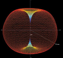
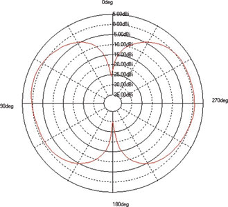
In mobile devices, no specific direction of radiation is emphasised. On the other hand, if the antenna is supposed to radiate in a specific direction, (ie, the antenna is designed to have some directive characteristics in its radiation pattern) then antenna gain is a better performance metric. It is possible that an antenna has good efficiency, but in some specific direction or directions the radiation pattern has a null and thus no radiation is recorded in that specific direction.
Gain
Gain is an antenna characteristic that combines the antenna’s efficiency and its directivity into one figure. Directivity means that the antenna radiates with greater efficiency to one particular direction in its surrounding space than to the others. Antenna absolute gain is defined as the ratio of the radiation intensity in a given direction to the radiation intensity that would be obtained if the power accepted by the antenna were radiated evenly to all directions of surrounding space (ie, isotropically). If no specific direction is stated, the direction of maximum radiation is used to determine gain. Directivity alone is pretty close to this, but actually it describes only the directional properties of the antenna and is therefore controlled only by the pattern. The term ‘antenna gain’ is actually a bit misleading, because an antenna is a passive component that does not have any amplifying characteristics.
The antenna’s radiation pattern sometimes is purposely steered to some specific direction. These so-called directional antennas are used commonly in base stations, but also in some other applications such as GPS where some directional characteristics are desirable. Since the GPS satellites are in the sky, the antenna should have the greatest radiating efficiency towards the upper hemisphere. Gain is measured in an anechoic chamber by feeding some power to the antenna and then measuring the strength of the radiated electromagnetic field in different angles of the surrounding space. From this data, the direction of maximum radiation is determined.
Gain is the measure usually used to measure antenna performance. It is a useful measure in cases where the antenna is required to have directional characteristics, for example in base stations situated on rooftops or at the end of office corridors, etc. and for GSM antennas used in some navigation applications. When directional radiation is needed, measuring gain determines if the power fed to the antenna is being optimally used. For example, in a wall-mounted base station antenna there is no point in directing the signal to the wall as it reduces the gain of the antenna to the preferred direction (assuming that the total efficiency level remains the same in both cases). Purely measuring antenna efficiency would provide the same performance information whether the antenna’s greatest radiation is directed optimally as intended or not.
Using gain as a measure of performance, even for directional antennas, has some disadvantages. For most mobile terminals, their orientation with respect to the closest base station is coincidental. The signal scatters and reflects several times from basically any object on its way from the base station to the mobile terminal. From the antenna point of view this means that the signal arriving to the receiver can pretty much arrive from any direction of the surrounding space and no optimal direction for receiving the signal can be determined in advance. Thus in mobile antennas, the antenna radiation pattern should be designed as omnidirectional as possible, making it equally effective in all directions. The fact is that an antenna with a high gain value in some specific direction may not receive the signals arriving from other directions very well.
Summary
Gain is the most prevalent way of measuring the efficiency of an antenna and, therefore, the performance of an antenna. However, gain does not measure the overall efficiency of an antenna. It only determines the efficiency of radiated output in one direction at a time. It tells nothing about the efficiency level that the antenna is achieving in all the other directions surrounding the antenna. That is fine if it is an application where all or most of the output from the antenna needs to be directed to a specific location and the location of the transmitting antenna is fixed with respect to the receiving antennas.
If, on the other hand, as in many other wireless applications including the use of mobile phones, the signal emitted from the antenna needs to be equally strong in more than one direction, then gain is a poor measure of performance. Although performance might be good when the signal is facing the direction of maximum performance, it could be weak, non-existent and/or degraded in other areas. Even if the signal is equally strong in all directions, gain does not provide a measure to determine that.
Because increasingly there are more applications that require a non-directed signal, companies are using radiated efficiency as the preferred test method. With radiated efficiency, one can determine what the efficiency and performance are for all areas surrounding the antenna. This knowledge enables the engineer to assess if the antenna will meet performance parameters or if it is necessary to design an antenna that gives maximum antenna performance uniformly or to multiple directions, rather than only in one direction. The antenna should have as omnidirectional a radiation pattern as possible because the likelihood for angle of arrival of the signal is uniformly distributed over the whole space.
© Technews Publishing (Pty) Ltd | All Rights Reserved