Industrial communication via fieldbus transceiver systems often requires long transmission lines. Designers, unaware of the large ground-potential differences (GPDs) between remote bus locations, either rely on the local earth ground as a reliable signal return path or directly connect remote grounds to each other, thus creating noisy ground loops.
In both cases, the integrity of the transmission signal is compromised, which can lead to system lockup and, at worst, destroy the bus transceivers. To make designers aware of these design pitfalls, this article explains where GPDs originate in the electrical installation, how ground loops are created unintentionally, and how isolation circumvents both conditions to yield a robust data transmission system.
Linking grounds
The link between the direct-current (DC) ground of a local electronic circuit and the earth reference potential of the mains is usually provided by the local power supply converting the line voltage into the required DC output.
Figure 1 shows a simplified block diagram of a low-cost switched-mode power supply (SMPS) typically used in personal computers, laser printers and other equipment. Here the DC ground of the SMPS output is referenced to the protective earth (PE) conductor of the mains via the SMPS chassis. This direct link, therefore, acts as a sense conductor, establishing the PE voltage as the local DC ground potential.

Linear and nonlinear loads
Large office and industrial buildings operate a vast number of nonlinear loads such as PCs, laser printers, solid-state heater controls, fluorescent tubes, uninterruptible power supplies and variable-speed drives. In comparison to linear loads such as incandescent lamps, whose phase currents maintain a sinusoidal waveform, nonlinear loads distort phase currents, introducing large harmonic content (see Figure 2).

While the third and fifth harmonics of the fundamental 50 Hz line frequency make up the lion’s share of the harmonic content, the vector sum of all frequency components (including the 50 Hz fundamental) can reach peak values that exceed the amplitude of the fundamental phase current by more than 100%.
All neutral conductors merge into one neutral conductor of large diameter within the distribution panel, running towards the transformer (Figure 5). In the case of linear loads, the neutral currents of multiphase systems cancel each other to a certain extent. Only a fraction of the total neutral current remains due to loading imbalance (Figure 3).

For nonlinear loads, however, the individual currents add up to a total neutral current consisting primarily of third harmonics (Figure 4). The large neutral currents of nonlinear loads, therefore, cause significantly higher voltage drops across the line resistance of the electrical installation than those of linear loads.

Earthing systems
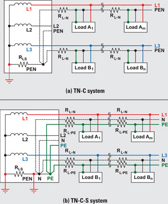
Most electrical installations use either the TN-C or the TN-C-S earthing system, both shown in Figure 5.

‘TN’ means the neutral is grounded to earth (French terre) at the transformer. The letter ‘C’ indicates the combined use of PE and neutral lines via one conductor, designated as ‘PEN’. The PEN runs through the entire system up to a distribution point (ie, a subpanel) close to the loads, where it is split into separate PE and neutral conductors that directly connect to the loads.
Although TN-C represents an old earthing system, it has regained interest because it is less costly than a system requiring an additional PE conductor. The TN-C method, however, has a major drawback. Because the split into PE and neutral lines occurs close to a load, the voltage potential at the local PE connection includes the large voltage drops across the line resistance, RL-N, of long neutral conductors. These voltage drops are caused by high neutral currents from nonlinear loads. The TN-C system, therefore, has the potential to cause large GPDs between remote grounds in the tens of volts.
The TN-C-S system reduces GPDs by starting an extra PE conductor within the distribution panel. Additionally, the star connection of the system’s neutral and PE conductors receives a second grounding to earth, reducing the equipotential at this point and counteracting the otherwise large voltage drop at the PEN across the source line resistance, RLS.
According to the United States National Electrical Code (NEC), the PE conductor is supposed to be currentless under normal operation. However, most nonlinear loads leak currents in the lower milliamperes into the PE conductor.
This amount, although small for one circuit, easily reaches amperes when hundreds of circuits contribute into the same line.
Although negligible in comparison with neutral currents, leakage currents do create potential differences between remote ground locations due to the voltage drops across the line resistance of the PE conductors. These GPDs, however, are in the millivolts range or lower and are thus significantly lower than in TN-C systems.
GPDs are not a problem for an electronic circuit limited to operation from only one local supply. GPDs do become of concern in the design of a communication link between two remote circuits (ie, fieldbus transceiver stations), each operating from a different supply.
Designing a remote data link
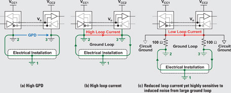
When designing a remote data link, the designer must assume that GPDs exist. These voltages add as common-mode noise, Vn, to the transmitter output. Even if the total superimposed signal is within the receiver’s input common mode range, relying on the local earth ground as a reliable path for the return current remains dangerous (see Figure 6a).

Any modifications of the electrical installation (ie, during regular maintenance work) are out of the designer’s control. The modifications can increase the GPD to the extent that the receiver’s input common-mode range is either sporadically or permanently exceeded. Thus, a data link that works perfectly today might cease operation sometime in the future.
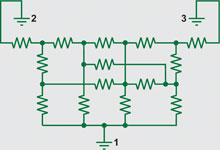
Removing the GPD by directly connecting remote grounds through a ground wire is also not recommended (Figure 6b). Bear in mind that the electrical installation constitutes a highly complex resistance network consisting of multiple cross-connected line and grounding resistances caused by multiphase systems, different cable lengths, and various grounding electrode paths (Figure 7).

A direct connection between remote grounds shunts this network while creating a current loop. The initial GPD tries to compensate its collapse by driving a large loop current through the low-impedance ground wire. The loop current couples to the data-line circuit and generates noise voltage that is superimposed on the transmission (common-mode) signal. This again carries the risk of a highly unreliable data transmission system.
To allow for a direct connection of remote grounds, the RS485 standard recommends the separation of the device ground and the local system ground via the insertion of resistors (Figure 6c). While this approach reduces loop current, the existence of a large ground loop keeps the data link sensitive to noise generated somewhere else along the loop. Thus, a robust data link still has not been established. The most robust RS485 data link over a long distance, withstanding GPDs of up to hundreds and thousands of volts, is via galvanic isolation of the signal and supply lines of a bus transceiver from its local signal and supply sources (Figure 8).

Supply isolators such as isolated DC-DC converters, and signal isolators such as digital capacitive isolators, avoid the creation of current loops and prevent current flow between remote system grounds with GPDs of up to several thousand volts.
Without a reference to ground, the bus transceivers would be operating from a floating supply. Thus, current or voltage surges caused by lightning, ground faults, or other noisy environments would be able to lift the floating bus common to dangerously high levels.
These events will not destroy components connected to the bus, as their signal and supply levels are referenced to the bus common and ride on the varying common reference potential. However, where the transmission wires connect to PCB connectors at the various transceiver nodes, the high voltages, if not removed, can lead to arcing and destroy PCB components close to the connector.
To suppress current and voltage transients on the bus common, it is necessary to reference the bus common at one point to the system ground. This location usually is at a non-isolated transceiver node, which provides the single-ground reference for the entire bus system.
While Figure 8 shows the detailed connection of two remote transceiver nodes, Figure 9 shows an example of an isolated data transmission system using multiple transceivers. Here, all but one transceiver connect to the bus via isolation. The non-isolated transceiver on the left provides the single-ground reference for the entire bus.

Conclusion
Designing remote data links requires the isolation of supply and signal lines of fieldbus-transceiver stations to circumvent the detrimental effects of GPDs and ground loops on the signal integrity and the components. While some of the figures in this article illustrate differential data transmission, the principles discussed also hold true for single-ended transmission systems such as RS232.

© Technews Publishing (Pty) Ltd | All Rights Reserved