
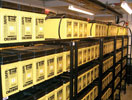
Nigel Scott, technical and business development manager at LEM, describes new approaches that enable standby battery systems to be continuously monitored during their service life, offering the capability to detect potential failures before they happen.
Over the last 30 years, the standby battery industry has become dominated by the valve regulated lead-acid (VRLA) battery, with its cousin, the gel battery. These high-capacity sealed cells are used to support a wide variety of critical systems. The batteries are held on a small continuous float charge, and this affects the failure modes of the cell.
Although based on slightly different chemistries, the characteristics of the VRLA (sometimes called the sealed lead acid (SLA), or activated glass mat (AGM)) and the gel battery have similarities, the main one being that they are both much more sensitive to temperature and charging conditions than their predecessor, the liquid electrolyte or ‘flooded’ cell.
Most VRLA batteries are charged at a fixed voltage of exactly 2,27 V per cell. Over-voltage during charging (more than 2,3 volts per cell for example) will cause the electrolyte in the glass pads to produce more gas than the recombination chemistry can cope with, and over time this will escape through the valve and be lost.
Temperature also plays a part. These cells are designed to last for up to 12 years. However, even if the charging voltage is correct, if the ambient temperature is too high, the cell will overcharge and moisture will again be lost.
Other problems can be failure modes such as early sulphation, poor connection between the posts and the grids, poor connection between the grids and the plates, stratification of electrolyte and accelerated grid corrosion.
If a cell anywhere in one of these batteries becomes open circuit (for example when the electrolyte dries out), then the battery cannot supply any current. If a few cells go short circuit (usually due to manufacturing faults), it is not as critical as an open circuit in the short term. However, the remaining cells in the battery are then being overcharged.
One of the most spectacular failure modes is thermal runaway, which is peculiar to VRLA and gel batteries. This is a positive feedback reaction, in which the higher float charge current tends, over time, to increase the temperature in the cell. This, in turn, causes the cell to take more float current and the process accelerates, resulting in fire or explosion. It is not common, but happens more often than is generally recognised. The only way to detect it is to monitor the internal cell temperature.
The traditional method of measuring the specific gravity of the electrolyte to estimate the capacity of each cell is not possible with VRLA or gel technology and the only certain method of determining to what extent the battery is capable of supporting its critical load has been by autonomy (discharge) testing the battery as a whole. Most installations have to be shut down during testing to avoid possible damage to their loads, and this can cause problems for the services they supply.
To avoid the high cost and disruption of these tests, non-intrusive electronic methods of continuous monitoring have been developed to determine in-service capacity. These systems aim to provide enough information about the battery to detect any incipient failures before they happen, hopefully extending the service life of the battery as well as preventing catastrophic failure during a power outage.
Today, the battery system parameter most commonly monitored is the terminal voltage of each cell or monobloc (a monobloc is two or more cells in the same case), although several manufacturers now monitor cell internal impedance as well – with varying degrees of success. In addition, even the most basic monitoring systems monitor battery charge/discharge current and ambient temperature.
Continuous battery monitoring is fast becoming generally recognised for its importance in lowering maintenance costs and helping to prevent catastrophic battery failure. However, it is very difficult to find a high quality product at a cost low enough for the average battery user.
Monitoring batteries intelligently
To address this need, LEM has moved from purely analog-based transducers into the area of intelligent components, with its Sentinel system. The Sentinel module offers comprehensive measured data and is based on a SoC (system on chip), jointly designed by LEM and a leading integrated circuit manufacturer. This is embedded in a module capable of measuring cell and monobloc terminal voltage, internal cell temperature and internal impedance, at a cost affordable by most battery system users.
Cell voltage is seen as the least important parameter, since the charger voltage dictates the overall voltage, and cells only deviate greatly from their individual nominal voltages when in the final stages of failure, probably too late to prevent a failure of the battery. Cell voltage monitoring is therefore of most use during a discharge due to a mains outage, or a discharge test, so that cells that are failing to meet specification can be detected and changed out.
Cell temperature can, on the other hand, be significant, since thermal runaway is a logarithmic progression and can normally be detected in advance of occurrence by trending the individual cell temperatures. Cell ‘simple’ (V/I) impedance is another significant parameter, which tends towards a logarithmic progression (Figure 1).
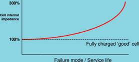
A failing cell can be 150 to 200% of its original ‘new’ value, while a completely exhausted cell is likely to be over 300% of the original value. There is no direct relationship between impedance/conductance/resistance and performance or end-of-life. However, trending the impedance value over time gives a good indication of possible failure and can certainly indicate cells that require further attention. All three are virtually identical in character and are promoted by different product manufacturers, depending on their products.
Impedance monitoring has not been the perfect solution to problem detection that it was hoped to be and some systems are seen as being inconsistent in failure detection. Recognising this, LEM has spent a great deal of time investigating the reasons for the fallibility of measurement versus failure detection and has developed a dependable test method, which penetrates well into the cell’s energy layer, to ensure a high degree of reliability.
It can be seen from Figure 1, however, that detection of a failure mode in its early stages is not easily achieved, and a problem may not be detected until the cell performance is significantly degraded. It would be of great benefit if the next generation of continuous standby battery monitors could give more information much earlier in the deterioration of the cell, whether due to a failure mode or natural causes.
To that end, LEM has been working on deriving more complex data from the cell or monobloc. The company has several patents in the area of cell parameter analysis, and the continuing developments will be incorporated into the next generation of cell interface module, designated ‘Lifeguard’.
The system that LEM is developing is based on the well-established electrical principle that any complex electrical circuit under stimulus can be represented by a simple equivalent, which exhibits exactly the same response characteristics. An electrochemical cell can be represented by such an equivalent circuit, and Figure 2 illustrates the standard circuit, known as the Randles equivalent circuit. There are more complex models, however the Randles circuit is more than adequate for the determination of first order parameters, such as capacity and condition or state of health.
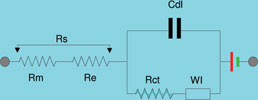
The Lifeguard system injects a complex test signal through the cell under test. The current waveform and the resultant voltage response are then recorded and post-processed using custom algorithms, to determine the Randles parameters, which are as follows:
* The metallic resistance (Rm) represents the resistance not only of the metal itself – posts, bus bars, grids and plates (paste) – but the efficacy of the joining between them.
* Electrolyte loss – represented by the electrolyte resistance (Re) – can be one of the main causes of premature cell failure.
* The double layer capacitance (Cdl) is a function of the effective plate area and the dielectric strength of the electrolyte.
* The charge transfer (Faradaic) resistance (Rct) is due to limitations in the rates of chemical reaction kinetics at the plate/electrolyte interface.
* The Warburg impedance (Wi) is representative of a diffusional mass transport process. It is, however, a low frequency component, not present during discharge.
* A pure electrical generation element, removed during the testing process.
The elements of the Randles circuit are representative of actual processes and/or failure modes experienced by the cell over its service life.
Figure 3 shows the progression of the parameters over the life of a cell. The same characteristics are also demonstrated during a discharge, or loss of capacity. As in Figure 1, it can be seen that resistance (simple impedance may be considered as resistance, since at practical test frequencies the relative contribution of the RC network to the overall impedance is not significant) is not the prime factor during the early stages of failure or capacity loss. Impedance alone therefore does not give any significant indication until the capacity loss is greater than perhaps 25–30%.
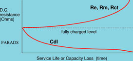
Since the industry standard is to replace batteries that fall below 80% of specified performance, it is clear that possible failure must be indicated far earlier than at present.
Unlike resistance, double layer capacitance differs significantly in the early stages of all failure modes, except purely metallic corrosion (Rm). There is a much more direct and quantifiable relationship between the prime health indicator, Cdl, and cell ampere-hours, and between the capacitance of ‘healthy’ and ‘poor’ cells of the same type, than there is between single value resistance and cell condition.
The monitoring technique
In the early stages of development, there were several problems to be overcome. The original algorithms were developed using a bipolar test signal. This was found not to be as reliable as unipolar test signals. However, on the switch to unipolar signals, one of the significant problems encountered was DC drift during the test.
LEM’s Lifeguard system is integral to each cell and uses a unipolar pseudo-random binary signal (PRBS) which draws current from the cell. This, however, will ‘micro-discharge’ the cell, the net effect of which will be reflected in the cell’s voltage response to the test signal (Figure 4a).
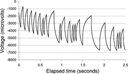
The underlying ‘DC’ trend in this type of data set can be seen in Figure 4b.
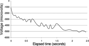
This drift distorts the cell’s transient discharge response depending on the number of cells per bloc, ampere-hour rating, condition and state of charge. Effective low-pass analog filtering is deleterious to the frequency ranges of interest, as they lie within the harmonic spectrum of the drift and are of the order of its fundamental. Simply removing the above trend does not preserve the characteristics of the data set necessary for correct parametric estimation. The underlying distortion must be removed in a way that will not distort the signal response.
By rearranging the varying frequency signal pulses in a frequency sweep, the cell voltage response can be made to follow a predetermined curve, eg, logarithmic (Figure 4c).
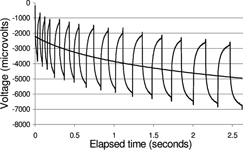
Once the underlying drift curve becomes uniform, firmware algorithms can then be designed to model the drift and remove it, resulting in a mean zero voltage data set suitable for direct input to the Sentinel algorithms (Figure 4d).
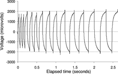
This method can reduce drift errors to less than 0,1%, without causing discernible distortion of the data set. Algorithms can then be applied to the measured waveforms, and the equivalent circuit parameters can then be derived with a high degree of accuracy.
Once the SoC can determine the cell’s real condition, several valuable additional functions can be programmed:
Terminal voltage optimisation (TVO): Due to variations in chemical constituents, the cells of a battery often have differing internal impedances. Since the charger fixes the terminal voltage of the battery as a whole, cells with higher impedances will manifest higher terminal voltages, and the lower impedance cells will take less. Over time, this can cause problems. In cells with a higher terminal voltage, it is likely to lead to accelerated positive plate corrosion and electrolyte loss. In lower voltage cells, it can cause accelerated sulphation.
With the SoC intelligent control system integral to the cell however, those cells exhibiting a higher than specified float terminal voltage can quickly be detected, and a system to ‘shunt’ the float current around the cell devised, thus optimising the cell’s terminal voltage.
However, float voltage optimisation can only be reliably carried out if the cell can be determined as being at maximum capacity without recourse to the terminal voltage, since this is controlled by the optimisation process. It may be that the cell actually requires a higher charge voltage to remain healthy, and ‘optimising’ without the required data may damage the cell.
Active charge management (ACM) for extended life: Tests carried out by battery manufacturers have indicated that the float current in VRLA cells is higher than that of flooded cells for the same terminal voltage. One effect of this is to accelerate positive plate corrosion and this can reduce the useful life of the cell by up to 30%.
Removing the float charge for a proportion of service life can reduce this effect, providing the cells do not suffer any measurable discharge in the process. In addition, the small pulses of charge current regularly experienced during life cycling can assist in preventing the formation of plate sulphation, without deleterious effects. This is a safer and more reliable form of the system becoming known in the industry as ‘opportunity charging’.
A useful side effect of life cycling is its ability to reduce the possibility of thermal runaway. This has been known to affect cells which are continuously subject to float charge, particularly when the battery in question is in a confined space or has little air circulation.
Lifetime data log of voltage and temperature: Manufacturers are continually pressed by standby battery system users for extended warranty periods, often of five years or more. In order to safeguard themselves, the manufacturers normally insist on periodic battery checks of voltage and temperature during the warranty period, sometimes with an annual discharge test. Since they are periodic and not within the control of the manufacturer, these checks are not always satisfactory and usually costly to the user. A cell-mounted module can provide a lifetime data log of terminal voltage and temperature to address this issue.
Exhaustive discharge protection (EDP): It is normal in charger/UPS systems, and even battery monitors, to preserve the battery by terminating a discharge based on the average cell voltage. This average is obtained by dividing the overall voltage by the number of cells in the battery.
The difficulty with this method is that weaker cells can be of a much lower terminal voltage than the battery average, and may be exhaustively discharged well before the battery as a whole has reached its termination voltage. This can damage these cells permanently, leading to premature failure in the long term. A highly accurate, dynamic ‘time to run’ (TTR) generic algorithm has been developed which will give warning if any individual cell is approaching exhaustion. Decisions may then be taken, possibly pre-programmed into the overview system, as to whether to shut down the UPS or reduce the less important parts of the critical load.
At the end of a discharge and recharge cycle – something that may only happen once a year or so in stationary batteries – the battery returns to a small maintenance charge, often called a ‘float’ charge. This charge is normally only about 1 milliamp per ampere-hour of battery and so is perhaps only a few hundreds of milliamps. If the cells experience a failure mode, this low current can change by several times its original level, and at the same time the internal temperature of the cell can rise or fall significantly.
It has historically been extremely difficult to accurately monitor and trend current at float levels of a few tens to a few hundreds of milliamps, since a discharge of several hundred amps will have to pass through the same transducer. This will cause remanence (hysteresis) in the transducer, and on its return to float levels the zero current point may have ‘jumped’ several amps, never to return to its original point. This, of course, makes trending impossible.
LEM believes that, to be meaningful, the monitoring of standby battery parameters must be as comprehensive as possible. To that end, in addition to voltage, impedance and discharge performance per cell, LEM already monitors internal cell temperature as standard. It is also developing a fluxgate-technology float-charge transducer capable of better than 10 mA resolution, with little or no temperature drift, and virtually no remanence after a high current discharge.
Taken as a whole, these advances can change the role of the battery monitor from an expensive addition, the cost of which is perceived to be of value only to the most sensitive installations, to that of a cost-effective integral life management system, essential to the service life of every VRLA battery.
| Tel: | +27 11 626 2023 |
| Email: | [email protected] |
| www: | www.denver-tech.co.za |
| Articles: | More information and articles about Denver Technical Products |

© Technews Publishing (Pty) Ltd | All Rights Reserved