Developed in the late 1990s to de-couple charging technology from battery chemistry and support platform independence for interchangeable battery modules, 'smart batteries' are popping up in everything from laptop computers and cellphones to cordless drills and handheld vacuum cleaners.
Several companies now sell off-the-shelf devices that implement standardised smart battery chargers and smart battery management circuits; but new battery chemistries and emerging application spaces are constantly pushing and stretching the fixed functionality of these devices to their limits. The Actel Fusion FPGA opens the door for a wave of innovation in smart battery management.
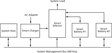
Illustrated in Figure 1, the smart battery concept defines interfaces, a data set, and behaviours of the smart battery, battery selector, smart charger, and host elements in a smart battery system. This article focuses on requirements for a smart battery and illustrates how Actel Fusion devices can be used to implement all of the necessary functions while leaving room for individual customisation.

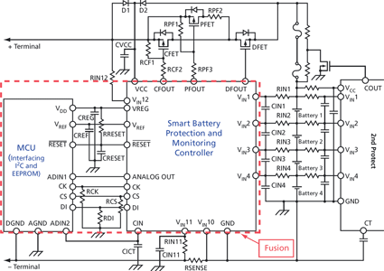
Figure 2 shows a typical smart battery implementation using off-the-shelf components. A smart battery generally contains one or more secondary battery cells, an analog monitoring chip, a digital controller chip, various discrete diodes, transistors, passive components, and a redundant safety monitor chip. All are used to monitor voltage, current, and temperature of the cells and manage proper discharge and charging of the battery pack within desired safety limits.

The Actel Fusion FPGA provides integration of analog monitor and digital control capabilities. Some manufacturers may prefer to maintain a separate second 'safety chip' for redundancy. The Fusion device has sufficient resources to allow extensive flexibility in implementation.
Analog functions
A smart battery controller must be able to measure the voltage of each individual cell within the battery pack. It must also measure charge/discharge current and temperature, and it must drive a number of external transistors to control discharge, charging, and fuse protection of the battery pack. To handle these functions, the Fusion device contains a number of analog input and output pins. These pins are arranged into groups called analog quads. Each analog quad then feeds an analog multiplexer, which in turn connects to an internal sample and hold circuit (S/H), and finally to a 12-bit analog to digital converter (ADC).
The analog quad can be configured to support voltage, current, and temperature measurements. Any of the three inputs can be configured to provide a single-ended positive or negative voltage measurement. Alternatively, the AV and AC inputs may be used as a differential pair to measure the voltage drop across an external current monitoring resistor, and AT can be configured to supply a small oscillating current to an external diode to measure ambient temperature at the diode location.
While most battery configurations will not require sampling of negative voltages, the ability to scale input voltages eliminates external components and improves precision for voltage measurements. For a typical 3-cell Lithium-Ion battery pack, the 12-bit A/D in an Actel Fusion FPGA provides voltage measurements with 4 mV resolution and unadjusted accuracy of 0,25 V - well within the limits required to control proper battery function.
In addition to the analog inputs, each analog quad contains a metal-oxide semiconductor field-effect transistor (MOSFET) control driver. These drivers have programmable drive strength and are designed to pull the gate of a power MOSFET to ground. They are ideal for control of the various MOSFET switches required in most smart battery implementations.
Unlike most off-the-shelf battery management devices, the Fusion device integrates an RC oscillator, eliminating the need for an external crystal oscillator. Coupled through one of the Fusion integrated PLLs and no-glitch multiplexer (NGMUX), this unique feature allows you to conserve power in the 'battery out' state by switching to a significantly slower processing clock without external components.
For smart battery applications, the Fusion realtime counter (RTC) can be used as an interval timer to periodically wake-up the device and update battery status when the controller is in standby mode. Additionally, this circuitry includes an activity detector that can be used to wake up the device whenever an external event, such as a button press or bus activity, is detected.
Lastly, the Fusion analog section contains an on-board voltage regulator to provide the 1,5 V core voltage for the Fusion device. Running the core of the device at 1,5 V cuts active power dissipation by half. This regulator has an internal shut-down mechanism associated with the RTC circuit described above. The shutdown circuit allows the FPGA logic to initiate standby mode by shutting down the regulator. Then the RTC can wake up the device by starting up the regulator when either an external event occurs, or when the RTC count reaches a programmed value.
Digital functions
Digital logic in the FPGA fabric can be used to implement the standard system management bus (SM Bus) interface, wake-up initialisation logic, shut-down state saving logic, and various state-machines or an embedded processor to sequence ADC conversions and perform the various calculations necessary to correctly monitor and control charging and discharging of the smart battery. Furthermore, FPGA logic can support unique design features like: battery authentication, additional safety features, unusual multicell configurations, or additional features not found in off-the-shelf battery controllers.
Nonvolatile memory (NVM)
For a smart battery application, the NVM is used to store variable states before entering standby or power-down sleep mode and for initialising them whenever the controller wakes. The NVM may also be used to implement ROM coded state machines or to store micro-code instructions for an embedded processor.
Nonvolatility
Nonvolatility is a key feature of the Fusion device that makes it suitable for smart battery applications. The Fusion device is truly live at power-up. The Flash-based FPGA fabric retains its programmed state even when power is removed (standby or sleep modes) and is ready for action immediately when core voltage reaches the turn-on threshold. This means that the Fusion FPGA can reliably control MOSFET states during the power-up ramp, and can respond to SM Bus commands and begin active monitoring within microseconds of a wake-up event.
Summary
The Actel Fusion FPGA melds all of the features needed to implement a standard smart battery monitor and controller. It handles measurements of analog voltage, current, and temperature. Fusion FPGAs include nonvolatile storage for battery state variables and processor code. In the Actel Fusion FPGA, flexible digital logic gates for state machines and embedded processor functions are fused together into a fully featured, single-chip solution that leaves plenty of room for creativity and innovation.
| Tel: | +27 11 315 8316 |
| Email: | [email protected] |
| www: | www.asic.co.za |
| Articles: | More information and articles about ASIC Design Services |
© Technews Publishing (Pty) Ltd | All Rights Reserved