


Many electronic systems include a realtime clock (RTC). The clock is used for many different functions such as keeping calendar time, time stamping and periodic activity initiation (eg, waking up regularly to make measurements). RTCs have been around for many years, but they have never been optimised for embedded applications. There are solutions available today that integrate an RTC with full-up 'standalone' functionality on an MCU, thus realising many benefits due to the tight coupling with the MCU. This article discusses how the amalgamation of the traditional RTC and MCU has resulted in a whole that is greater than the sum of the parts.
Keeping time
Figure 1 illustrates a block diagram of a smaRTClock module from Silicon Laboratories. This circuit will perform all the conventional functions associated with an RTC (timekeeping, alarm and operation when the main system is switched off) as well as certain 'failsafe' functions such as recovery from power failure or clock source failure.
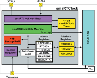
The base timer unit in the smaRTClock is a 47-bit free-running counter. This can be based on the 37,768 kHz crystal or can even use an internal self oscillator mode that operates at 20 kHz or 40 kHz (the self oscillator consumes less power but is less accurate). When a crystal is connected, the least significant bit in the second free-running counter byte, transitions precisely every second. Software is used to determine calendar time from the free-running counter. There is no need to have an extra set of registers that keep calendar time denoted in conventional units of time.
One advantage of this software approach is that the user has more control over the operation since the algorithm can be as complex or simple as the system requires. For example, temperature compensation, which typically complicates things, may be incorporated into the algorithm using the on-chip temperature sensor. Alternatively, if the system does not need to wake often (for example, a swimming pool pump timer that wakes up only once a day), then the overhead required to implement this control is trivial.
There is a set of three interface registers that control the internal registers in the SmaRTClock module. This keeps the number of special function registers required to a minimum and also provides a level of abstraction so that the counter cannot be accidentally modified. The alarm register can be set to provide a hardware interrupt when the free-running 47-bit counter corresponds to a value that action needs to be taken. This type of functionality is also known as 'output compare'.
An MCU may include a low-power mode called 'suspend' mode. In this mode, it is possible to wake up (without resetting the device) within a single system clock cycle when there is an alarm interrupt from the smaRTClock module.
Temperature compensation
Temperature-compensated crystal oscillators and temperature-compensated RTC chips are relatively expensive compared to components that have no temperature compensation. It is necessary to have some form of temperature compensation to achieve timekeeping accuracy over a wide temperature range. The frequency of crystal oscillators tends to drift with changes in ambient temperature as well as voltage supply and age.
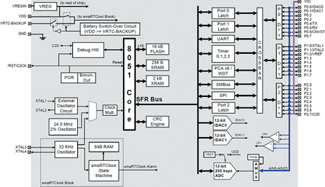
Fortunately, the C8051F410 MCU (shown in Figure 2) includes an on-chip temperature sensor that is ±3% accurate, enabling the timekeeping algorithm to incorporate the information from the on-chip temperature sensor to implement compensation. The benefit is that a lower-cost crystal oscillator that does not have integrated temperature compensation, can be used in the system.
In order to implement the temperature compensation algorithm, the ambient temperature is measured once per minute using the on-chip temperature sensor. In most operating environments, the temperature is not expected to change much in this timeframe. The value is then used to calculate the deviation (in ppm) and store this result (the number of microseconds to be compensated) in a memory location. The value calculated for each minute passed, is accumulated during the day, and at the end of the day, the algorithm will compensate the time lost.
There are a number of other features shown in Figure 2 that pertain to the smaRTClock functionality such as: the power sources, battery switchover circuit, clock sources, back-up RAM and the RTC block itself. The real benefit, however, is the combination of these features on a single chip without the overhead of requiring two or more standalone chips communicating data to each other.
Dealing with power failure
An on-chip voltage regulator can be connected to any voltage from 2,0 V to 5,25 V. The actual voltage used to power the CPU is 2,5 V, although this is decoupled from the I/O system of the chip so that the MCU can be used in a wide range of systems (from 2,0 to 5,25 V) without external interfacing required. A VIO pin can be tied to the system voltage supply so that the I/O will operate at the same level as any other devices in the system. In addition to the main power supply, a VBAT input can be tied to a battery operating as low as 1,0 V. This provides the 'backup' power for the SmaRTClock.
The first benefit of the integrated smaRTClock is that if the system power supply falls below VBAT, the on-chip battery switchover circuit will automatically switch the smaRTClock to the back-up battery. This means that, in the event of a power failure, the RTC will continue to operate, and the dedicated backup RAM in the smaRTClock module will be maintained. By implementing simple software that periodically stores a system status snapshot in this backup RAM, the system can recover to a known state and key data that the system has been measuring will not be lost when the main power supply comes back on-line. When the MCU is reset, a routine is initiated to check the reset sources register to determine that system power has been lost; then, the reset routine reads the contents of the backup RAM and restores important data to the CPU and working registers. For example, if the device was used in a utility meter, it could easily keep track of the dates and times that power was lost and for how long it was lost and still maintain accurate information on consumed units prior to the loss of power. When the main power is restored, the battery switchover circuit reconfigures the MCU power supply automatically so that the battery backup source is switched off. This ensures that the life of the backup battery is optimised.
Dealing with clock failure
For conventional systems using standalone components, clock failure is a potentially greater problem than power failure. Usually, the system clock for the C8051F410 chip would be generated by a 24,5 MHz on-chip oscillator that was multiplied to 49 MHz with 2% accuracy (across voltage and temperature). It could also use an external crystal, although that is not necessary as the on-chip oscillator is accurate enough to operate the internal functions as well as the serial communications within specification. The smaRTClock would be connected to a low-cost 32,768 kHz crystal on the XTAL 3 and XTAL 4 pins. The crystal derives its power from these pins through the smaRTClock module, which is true whether the smaRTClock is being sourced from the main or the battery backup.
In a conventional system, if there is a problem with the 32,768 kHz crystal, the system would suffer an unrecoverable failure as the RTC source is lost. However, with the integrated SmaRTClock, there is an independent missing clock detector circuit. Crystal failure will cause a device reset and set a flag indicating that the crystal has failed in the reset sources register. When the MCU is reset, the last saved system status information can easily be recovered from the backup RAM, which is still powered by the backup battery.
The 32,768 kHz crystal can also be routed into the main system clock path, so that it is possible to run the MCU at low frequency. This can be used in systems that cannot be 'put to sleep' periodically but must run in a low-speed/low-power mode continually.
There are obvious benefits to integrating commonly-used functions into MCUs. Functions such as periodic waking up, service reminders and time stamping are used in many systems from meters to point-of-sale terminals to data loggers. It is also very beneficial to be able to incorporate 'failsafe' features that allow recovery of the system in the event of power or clock failure while maintaining 'last known' system status information.
The smaRTClock has added useful features because it can wake-up very quickly (within a single system clock cycle) from suspended operation to resume execution at full system clock speed as well as the three key failsafe features: keeping the clock alive in the event of a power failure, keeping the system alive in the event of a clock failure and the ability to recover from system failure by restoring the last known system state.
For more information contact Rob McMaster, NuVision Electronics, +27 (0)11 894 8214, [email protected]
| Tel: | +27 11 608 0144 |
| Email: | [email protected] |
| www: | www.nuvisionelec.com |
| Articles: | More information and articles about NuVision Electronics |


© Technews Publishing (Pty) Ltd | All Rights Reserved
 printer friendly version