
There is a new family of DC/DC converters that do not work in the traditional PWM (pulse width modulation) or PFM (pulse frequency modulation) mode but in the 'hysteretic' mode.
This article introduces the concept, explains the technology and shows what to look out for when designing with them. Hysteretic Mode controllers are becoming popular amongst designers due to easy usage and the necessity to work extremely cost effectively.
Traditionally 'hysteretic mode' is not a mode that advanced DC/DC converters were designed for. It was just a mode that a converter would run into when the operation mode of choice would not be able to control the output voltage anymore. In such a case the output voltage would be limited by an over-voltage protection with a certain hysteresis that would protect external components from getting damaged.
In such operation, the converter would turn off, after activating the over-voltage protection and stay off for a certain amount of time or until the voltage would go low enough to a fixed level. This continuous switching on and switching off of the converter would look like a hysteresis curve and this is the reason why the mode is called 'hysteretic mode'.
Today, some nice features of hysteretic controllers make this mode of operation so popular that large semiconductor manufacturers such as National Semiconductor introduced a hysteretic mode converter last year and is soon to release another.
The hysteretic control
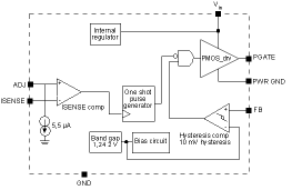
To explain the concept of such a converter, Figure 1 shows the basic control loop of National's LM3485 Hysteretic controller. The output voltage is sensed through the feedback pin just as in any other DC/DC converter by a comparator that is comparing the feedback voltage with an internal reference voltage. In PWM and PFM controllers this comparator is called an 'error amplifier'. In hysteretic mode it is called a 'hysteretic comparator'.

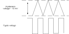
Not only the name is different, also the function varies. The hysteretic comparator has two fixed thresholds in which the feedback pin voltage moves. The LM3485 has a 'hysteretic window' of 10 mV. Figure 2 shows the feedback voltage between the threshold voltages and the corresponding behaviour of the Pgate.

This way of controlling a DC voltage has some advantages and some disadvantages. Positive arguments are the easy control loop. It is very easy to get such a controller stable. Long calculations or exhausting iterations to find the right compensation components are not necessary. The control loop is not only very stable but also extremely fast with a delay response of only about 90 ns. This, in combination with a very large duty cycle range of up to 100% yields an extremely fast transient response. It is superior to competing regulator architectures as PWM current mode or voltage mode. The LM3485 has a duty cycle range from 100 ns minimum on time up to 100%. Also features like a pulse skip mode in light load operation are a given in hysteretic mode designs.
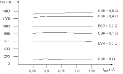
As mentioned, there are some disadvantages. As the switching frequency is not set by a controlled oscillator, it will vary with different external components and with input voltage changes. If the switching frequency has to be fixed in a certain application it might be difficult to find the right design. The factors that define the switching frequency the most are the input voltage, the inductivity value of the inductor and the ESR of the output capacitor. As many capacitors change their ESR over temperature, the switching frequency will change as well. A good trick to fix the ESR of the output capacitor is to use a ceramic capacitor that has a very low maximum ESR (over-temperature and frequency) of about 10 mΩ. Using such a capacitor and putting a small resistor in series will simulate a fixed ESR. Figure 3 shows measurements taken with different ESRs of the output capacitor. As many factors determine the operating frequency, the exact values given should only be regarded as general guidelines.

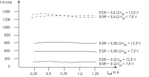
Besides the frequency variation caused by the selection of the output capacitor, there is also the influence of the inductor size. Over a certain inductance range it can be said that the larger the inductor the lower the frequency. The input voltage also affects the switching frequency. So in designs where the input voltage range is rather limited the switching frequency is easier to control then in very widely specified Vin ranges. Figure 4 shows the effects on the switching frequency upon input voltage variations.

As all the effects discussed in the previous paragraph, as well as factors like the layout have an influence on the frequency behaviour, it is rather difficult to build a reliable mathematical model of the regulator. In some cases where switching frequency considerations are a must, this is a disadvantage. To get a rough calculation on the frequency the circuit will work at the following formula can be used:

The component delay includes the component's propagation and pFET delay times. It can be taken from the individual datasheet. A more detailed formula would include the ESL component of the output capacitor as well. As this value usually is not given by the capacitor manufacturers it usually is not of much help in any case.
Output voltage ripple
On the first look, the output voltage ripple should be defined by the hysteresis at the 'hysteretic comparator' only. So in the case of the LM3485 this would be 10 mV. Because of the effect of the resistive divider in the feedback path that 10 mV ripple at the reference voltage of 1,242 V equals about 40 mV hysteresis on an output voltage of 5 V. Unfortunately again, calculations are not that simple because there are other factors that determine the output voltage ripple. One of them is the delay from equation 1. A way to influence the delay of the regulation circuit is to use a 'speed up' cap in parallel to the top feed-back resistor. By this, the output ripple can be decreased but operating frequency is increased.
Example of a typical design process
A designer is working on a power supply for a consumer application with the following specifications:
Input voltage is 5 V and the output voltage is supposed to be 2,5 V at 3 A. Efficiency should be at least 80% and output ripple must be below 50 mV. The switching frequency is supposed to be rather fixed at 300 kHz. But most important is number one to number three criteria: cost, cost and cost...
Easiest way of setting up a quick working design would be to take one of National Semiconductor's LM3485 evaluation boards and to adjust the external components to the specific values needed. These values can be calculated with the given formulas of the datasheet. After powering up the design for the first time, the designer notices that the switching frequency is lower in reality than what the results of the formulas were suggesting.
Reason for this is that the output capacitor's ESR value used by the designer is only a max specification given by the manufacturer. Most capacitor manufacturers will not give the exact value. Also the value of ESR will change quite a bit over temperature.
Increasing the switching frequency can be achieved by reducing the inductivity (L) or by increasing the value of the ESR of the output capacitor. Because using a smaller inductor saves some money too, this is what we decide to do. The ESL of the output capacitor and the layout will have an effect on the exact switching frequency and ripple of the design as well. So after the final layout is done it is a wise thing to check the functionality again and make further adjustments if necessary.
Wrapping up
This article explained how a hysteretic mode controller operates, when to use such a control scheme and when not to. Also, it showed in an example how to design with such a DC/DC controller concept. Using a hysteretic mode controller is a great alternative for cost driven applications where switching frequency does not have to be fixed and where easy and simple design work is appreciated. Further information on the LM3485 Hysteretic Mode Controller can be found at www.national.com.
For more information contact Simon Churches, Arrow Altech Distribution, 011 923 9600, [email protected].
| Tel: | +27 11 923 9600 |
| Email: | [email protected] |
| www: | www.altronarrow.com |
| Articles: | More information and articles about Altron Arrow |

© Technews Publishing (Pty) Ltd | All Rights Reserved