


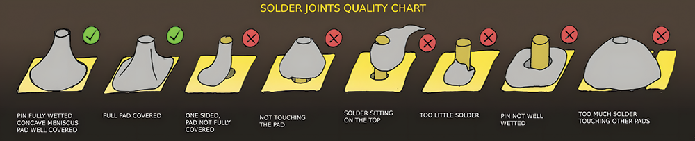
 Figure 1. Solder joint quality for through-hole components [source: seeedstudio.com].
Wire soldering operations are still widely accepted in the electronics assembly industry. When a product, or the parts within, cannot withstand the heat of oven reflow, the localized heat provided by a soldering iron has been the traditional solution. In high-volume operations, this can often require large labour pools to keep up with more automated assembly processes upstream or downstream. Soldering with wire and iron also leaves process judgments up to individual operators, and can produce a wide variety of defects, scrap, or long-term quality issues.
Despite the many improvements in automated soldering technology through the years, many soldering operations are best suited to manual production methods, which produce inconsistent results. Whether in low-volume custom operations or large-scale manufacturing processes, the quality of hand-soldered joints will exhibit a high degree of variation. Defect, scrap, and rework rates can be excessive, even when using skilled employees.
Higher temperature lead-free operations present an additional challenge. Because of the higher temperatures required, these processes have even smaller operating windows. Visual inspection of lead-free solder joints also presents new difficulties, and since most hand soldering rework occurs on-the-fly, actual defect rates are difficult to measure.
There are other process solutions available which involve very little capital expenditure, but can significantly increase operator output. These solutions are effective in eliminating many of the process defects associated with wire solder. They will usually result in a faster and more controllable process that reduces scrap and improves overall product quality. In many applications where wire solder was once a requirement, a more automated approach can often be achieved using solder paste and localised heating methods.
Identifying hand-soldering defects
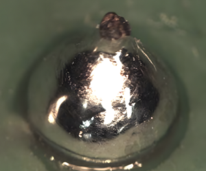
Too much solder
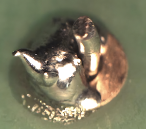
Excessive solder can be caused by operator error and flux core solder wire quality variation. Even the best operator cannot get solder to wet when they reach a section of wire where the flux core is reduced or missing entirely. An excessive solder joint causes poor contact angles, stress concentration points, and can even result in bridging between components (see figure 2).
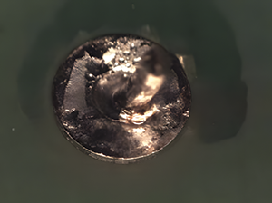
Not enough solder
An insufficient solder joint is at risk due to poor mechanical strength. In surface mount applications an insufficient joint can be difficult to see because so much of the solder joint is under the component lead. In through hole applications, there can be poor hole fill that is not visible (see figure 3).
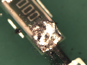
Overheating
Leaving the iron in contact for too much time, or having too high an iron temperature can damage components and circuit boards. The burns are a defect that is easy to detect. Less easy to detect are cracked components that can easily make it to the field before making their presence known. Component cracking is caused by thermally induced expansion mismatch (see figure 4).
Contamination
High iron temperatures and inadequate iron maintenance can leave behind burned flux and oxidised solder. Conversion to lead free solders typically requires higher iron temperatures that aggravate flux burning. Burned flux residue can contaminate joints, causing voids and interfere with wetting by covering surfaces that should be soldered (see figure 4).
Cold joints
Insufficient heating and insufficient flux content in wire can both result in joints where the solder does not wet well. There is a minimum activation temperature below which the flux will not properly remove metal oxides. All the surfaces to be soldered must reach a minimum temperature for intermetallics to form. Putting a drop of molten solder on a piece of copper will not result in a joint unless there is enough heat in the molten solder to heat the copper to that temperature.
Also, solder alloys wet and spread better the higher the soldering temperature. This improved wetting is caused by changes in surface tension and intermetallic growth rate. Poor wetting results in lower joint strength, voiding, and in some cases no joint at all (see figure 5).
Solder spikes and icicles
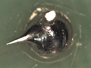
Solder spikes have been reported as the most common soldering defect. They are the result of several bad techniques. Poor soldering iron technique can draw spikes of solder by allowing the joint to partially solidify before the tip is removed. Insufficient heating can be difficult for even a skilled operator to overcome and could also result in solder spikes. Many of the more inexpensive irons available have poor iron temperature control, which could also cause spikes (see figure 6).
The issue of flux consumption also produces solder spikes. Solder re-oxidizes when heated and insufficient fluxing action results in an oxide shell that increases the probability of a solder spike. Solder spikes are vulnerable to touching other electrical components and could break loose short-circuiting signals.
All these defects have a common root cause. They are the result of a manual operation, and manual operations by definition are more likely to cause variation. Handmade items have value when we are looking for unique products, but ‘one-of-a-kind’ is not a selling point for solder joints.
Employee training is essential to making good solder joints, but training courses cost money and take away from valuable production time. Even highly trained and skilled employees must deal with the effects of fatigue. High rates of employee turnover result in even more training expense, and smaller operations with fewer trained employees must find ways to deal with absenteeism and vacation time.
Evaluating the true cost
Solder material: Solder wire is sold as a commodity. The percentage of a product’s cost from solder is usually quite low and may not even be on the bill of materials. The difference in performance between solders can result in yield loss change of 50% or more. Compare the cost of scrap to the cost of solder and you will usually find the solder cost is insignificant.
Inspection costs: These are the costs associated with lost productivity from time spent inspecting solder joints for defects. The operator may perform this inspection as the joints are manufactured, or it may involve secondary or even tertiary inspection operations. Inspection costs increase when there are customer complaints and returns that require corrective action.
Rework costs: This is the cost of time spent remanufacturing a product and the materials consumed in repeating the soldering operation a second time. This rework can take place immediately as the joint is made, or can result from postproduction inspection and rejection.
Scrap costs: Perhaps the most devastating cost is when a defective solder joint cannot be reworked, or results in damage to the product. This cost includes the cost of the raw materials, and all the value-added time invested.
Training costs: The manual production of solder joints requires skilled employees, and skilled employees require training. In addition to the actual hours spent in training and certifying employees, there are the costs of training materials and instructors. There is also the cost of ‘on-the-job’ training. Skill derives not just from training, but also from experience. Training continues on the production floor, and experience is making a mistake, correcting for it and learning from it. All this happens at the expense of effective production.
Complaints and returns: In addition to the direct costs of dealing with customer complaints and returns, there is the intangible cost of future business being lost because of poor quality. In some cases, a customer will only require replacement, which more than doubles your cost of manufacture for that sale. In others, they require the implementation of corrective action which does much more than double costs in the short term.
| Tel: | +27 11 473 2149 |
| Email: | [email protected] |
| www: | www.priben.co.za |
| Articles: | More information and articles about Priben |


© Technews Publishing (Pty) Ltd | All Rights Reserved
 printer friendly version