In an ideal RF system, all the energy from the RF source is transferred to the load. An example of this would be a transmitter delivering a signal to an antenna with the interconnect between the two signal chain components operating at 100% efficiency. However, this does not happen, and factors like impedance mismatch and losses need to be considered. There are a few well established methods of discussing these imperfections and ways to include this in a system design. This article strives to be a brief primer on this topic.
RF energy in a signal chain
An RF signal chain is merely a system of connected RF components and devices in which a signal flows from a source to a load. This could be a transmitter signal chain, receiver signal chain, or really any RF system.
Leaning on the Law of Conservation of Energy, all the signal energy injected into a signal chain needs to go somewhere. Generally, every node of a signal chain exhibits loss and mismatch. As the signal energy from a source passes through signal chain components, devices, and interconnect, some of the signal energy is transferred through, some is reflected back, and some is absorbed within the signal chain elements.
Insertion loss/transmission loss
The insertion loss of a signal chain element is simply the amount of signal energy that is absorbed or otherwise extracted from the signal chain by that element. Hence, the ratio of the incident (forward/incoming) power to the transmitted (through) power is the insertion loss. This ratio is usually given as a logarithmic quantity in terms of power (in decibels), but can also be measured in terms of voltage, which is less common.
Return loss
The return loss from a signal chain element is the amount of signal energy reflected from the incident node of that element compared to the total incident energy. The reflection loss differs from insertion loss because the return loss signal energy isn’t being lost within the signal chain element, but rather, is reflected back into the signal chain opposite the incident node. Like insertion loss, return loss is also generally described in decibels of power.
VSWR
Voltage standing wave ratio (VSWR), often referred to as standing wave ratio (SWR), is the ratio between the transmitted and reflected voltage standing waves at a signal chain element incident node. VSWR is most often described as a function of the reflection coefficient at the input of a signal chain element. Due to this, the VSWR is also a measure of how efficiently RF energy is transferred from a source to a load. An ideal system with perfect match (no reflection) would result in a VSWR of 1:1. However, real systems always have some degree of mismatch, making the VSWR larger than 1:1, and the higher the ratio the worse the match.

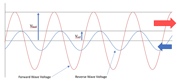
VSWR can be expressed in terms of the forward and reflected wave voltages and can therefore be calculated as:
With these voltages indicated in the following graph.

Therefore, using the reflection coefficient, VSWR is:

Where Γ, the reflection coefficient, is defined as the ratio of the reflected voltage vector to the forward voltage.
For more information contact Andrew Hutton, RF Design, +27 21 555 8400, [email protected], www.rfdesign.co.za

© Technews Publishing (Pty) Ltd | All Rights Reserved