


Power analysis involves some measurements, terms and calculations that may be new and possibly confusing to engineers and technicians who are new to this discipline. Today’s power conversion equipment often produces complex voltage and current waveforms that may require different methods than once applied for simpler sine waves.
This article introduces the basic concepts of power measurements and clarifies the definitions of key terms such as:
• Root mean square.
• Real power.
• Apparent power.
• Power factor.
• Crest factor.
• Harmonic distortion.

Developing a better understanding of these measurement terms and concepts, as well as the relationships between them, will help to better interpret measurements encountered when testing designs.
RMS (root mean squared value)
The RMS value is the most commonly used and useful means of specifying the value of both AC voltage and current. The RMS value of an AC waveform indicates the level of power that is available from that waveform, this being one of the most important attributes of any AC source.
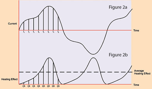
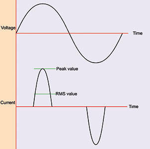
The calculation of an RMS value can best be described by considering an AC current waveform and its associated heating effect such as that shown in Figure 2a. If this current is considered to be flowing through a resistance, the heating effect at any instant is given by the equation:
W = I²R
By dividing the current cycle into equally spaced coordinates, the variation of the heating effect with time can be determined as shown in Figure 2b. The average heating effect (power) is given by:
In order to find the equivalent value of current that would produce the average heating effect value shown above, then the following applies:
Therefore:

= the square root of the mean of the squares of the current
= the RMS value of the current.
This value is often termed the effective value of the AC waveform, as it is equivalent to the direct current that produces the same heating effect (power) in the resistive load.
It is worth noting that for a sinusoidal waveform:

Average value
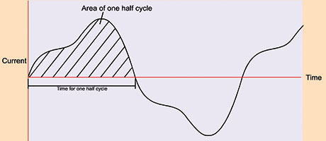
The average value of a waveform such as that shown in Figure 3 is given by:
Notice that the average value can only have real meaning over one half cycle of the waveform since, for a symmetrical waveform, the mean or average value over a complete cycle is zero. Most simple multimeters determine AC values by full-wave rectification of the AC waveform, followed by a calculation of the mean value.
Such meters, however, will be calibrated in RMS and will make use of the known relationship between RMS and average for a sinusoidal waveform, i.e.:
RMS = 1,1 x mean
However, for waveforms other than a pure sine wave, the readings from such meters will be invalid. Because of this, oscilloscopes, power analysers and high-quality multimeters directly measure RMS values instead of inferring them based on rectified waveforms.
Real and apparent power (W and VA)
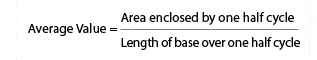
If a sinusoidal voltage source of, say, 100 VRMS is connected to a resistive load of, say, 100 Ω, then the voltage and current can be depicted as in Figure 4a and are said to be ‘in phase’. The power that flows from the supply to the load at any instant is given by the value of the product of the voltage and the current at that instant, as illustrated in Figure 4b.
Notice that the power flowing into the load fluctuates (at twice the supply frequency) between 0 and 200 W and that the average power delivered to the load equals 100 W. The average of the instantaneous power values is the real power (sometimes called active power). This is the power available to the load to do real work and it is given in watts. Note that with a purely resistive load, the RMS voltage (100 VRMS) can be multiplied with RMS current (1 ARMS) to get real power (100 W).
Now let’s consider a more realistic load. Real-world loads are reactive, that is, they have some inductance and capacitance as well as resistance. For example, let’s assume a load with a resistance and dominant inductance that combine to form a 100 Ω impedance. The current flow will still be 1 ARMS, but the current flow will no longer be in phase with the voltage. This is shown in Figure 5a by the current lagging behind the voltage by 60°.

Although the power flow continues to fluctuate at twice the supply frequency, it now flows from the supply to the load during only a part of each half cycle – during the remaining part, it actually flows from the load to the supply. The average net flow into the load, therefore, is much smaller than in the case of a resistive load as shown in Figure 5b – with only 50 W of useful power (that is, real power) delivered into the inductive load.
To determine the real power, the same technique is used as in the first example. Voltage and current are measured at simultaneous points on the waveform, multiplied, and then the average value taken. This method of calculating real power is effective regardless of phase shift or waveshape.
In both of the above cases the RMS voltage was equal to 100 VRMS and the current was 1 ARMS. However, in the case of the reactive load, the real power was not equal to VRMS x IRMS. That is, the load had 50 W available to perform work, instead of 100 W. Unfortunately, the power system still has to carry the full 100 W, even though it is not useful. The product of RMS voltage and RMS current is expressed in units of volt-amperes (VA) and is defined as:
Apparent Power – VRMS x ARMS
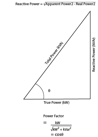
Sometimes it is helpful to consider the difference between apparent and real power. The vector difference between apparent power and real power is known as reactive power and it is measured in volt-amperes, reactive (VAr). The measurement of reactive power assumes that apparent power, real power and reactive power form a right triangle with apparent power as the longest leg (hypotenuse). Thus:
However, this relationship only holds true for sinusoidal waveforms, which are increasingly rare in today’s power electronics devices. The real power delivered depends in part on the nature of the load. It is not possible to determine the value of real power from the knowledge of RMS voltage and current. This can only be achieved (e.g., for assessing heat loss or efficiency) through the use of a true AC power meter, or oscilloscope, capable of computing the product of the instantaneous voltage and current values and displaying the mean of the result.
Power factor
It should be clear by now that in contrast to DC systems, and except for pure resistive loads, the transferred AC power is not simply the product of the RMS voltage and RMS current values. One way of expressing the relationship between apparent power and real power is with the notion of reactive power, which has already been covered. However, in most applications, a simple ratio between real power and apparent power is easier to grasp and apply. The ratio is called power factor, and it’s defined as:

In the previous example, the useful power (50 W) was exactly one half of the apparent power (100 VA), so the power factor is 0,5 or 50% (note that the units of power factor are dimensionless). In the case of sinusoidal voltage and current waveforms, the power factor is actually equal to the cosine of the phase angle (θ) between the voltage and current waveforms. For example, with the inductive load described earlier, the current lags the voltage by 60°. Therefore:
PF = cosθ = cos 60° = 0.5

This is why power factor is often referred to as cos. It is, however, important to remember that this is only the case when both voltage and current are sinusoidal [Figure 6 (I1 and I2)] and that power factor is not equal to cos in any other case [Figure 6 (I3)]. This must be remembered when using a power factor meter that reads cos, since the reading will not be valid except for pure sinusoidal voltage and current waveforms. A true power factor meter will compute the ratio of real to apparent power as described above.
Crest factor
It has already been shown that for a sinusoidal waveform:
The relationship between peak and RMS is known as the crest factor and is defined as:

Thus, for a sinusoid:
Many items of modern equipment connected to the AC supply take non-sinusoidal current waveforms. These include power supplies, lamp dimmers and even fluorescent lamps.
A typical switch-mode power supply (SMPS) will take current from the AC supply as shown in Figure 7. It is clear that the crest factor of the current waveform depicted is much greater than 1,414 – indeed, most switch-mode power supplies and motor speed controllers have a current crest factor of 3 or greater.
It follows, therefore, that a large current crest factor must put additional stress on equipment supplying such a load, as the equipment must be capable of supplying the large peak currents associated with the distorted waveform. This is particularly relevant where a limited impedance power source, such as a standby inverter, is supplying the load. It is thus clear that, where AC equipment is involved, it is important to know the crest factor of the current drawn as well as its RMS current.
Harmonic distortion
If a load introduces distortion of the current waveform, it is useful, in addition to knowing the crest factor, to quantify the distortion of the wave shape. Observation on an oscilloscope will indicate distortion but not the level of distortion.
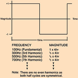
It can be shown by Fourier analysis that a non-sinusoidal current waveform consists of a fundamental component at the supply frequency plus a series of harmonics (i.e. components at frequencies that are integral multiples of the supply frequency). For example, a 100 Hz square wave consists of the components shown in Figure 8.
A square wave is clearly very distorted compared to a pure sine wave. However, the current waveform drawn by, for example, an SMPS, a lamp dimmer or even a speed-controlled washing machine motor can contain harmonics of even greater significance. Figure 9 shows the current drawn by a popular SMPS model together with the harmonic content of that current.
The additional harmonic current not only flows within the power supply itself, but in all of the distribution cables, transformers and switchgear associated with the power supply, and will thus cause additional loss.

There is an increasing awareness of the need to limit the level of harmonics that equipment can produce. Controls exist in many territories to provide mandatory limits on the level of harmonic current permitted for certain types of load. Such regulatory controls are becoming more widespread with the use of internationally recognised standards such as EN61000-3. Thus, there is a need for an increased awareness amongst equipment designers as to whether their products generate harmonics and at what level.
| Tel: | +27 10 595 1821 |
| Email: | [email protected] |
| www: | www.comtest.co.za |
| Articles: | More information and articles about Comtest |


© Technews Publishing (Pty) Ltd | All Rights Reserved
 printer friendly version