


LED lighting and especially intelligent LED lighting is gaining popularity. One of the most interesting and fastest growing segments is architectural lighting where high-quality colour mixing is an important requirement. Intelligent LEDs are also increasingly sought after in commercial and residential lighting.
Meanwhile LED prices are constantly dropping and LEDs are becoming affordable for an ever wider set of new applications.
For all these applications, the brightness, colour and dynamic behaviour of LEDs need to be controlled as accurately, precisely and cheaply as possible. To control the brightness of an LED, its current needs to be controlled. There are two methods to control the perceived brightness of LEDs: analog dimming and modulation dimming.
Analog dimming increases or decreases the LED current to increase or decrease the LED brightness. The disadvantages are that the relationship between LED current and luminous intensity is not linear, and the LED colour temperature may be different at different current levels.

For colour mixing it is preferable to fix the LED current and control perceived brightness by modulating this current. By modulating we really just mean turning the LED on and off very quickly. If the switching rate is high enough (above the flicker fusion threshold) then the human observer sees it as a constant light source due to persistence of vision. It is then the average proportion of time the LED spends turned on that determines the brightness.
Flicker fusion threshold is subjective, statistical and depends on the integration times of the different photoreceptor cells (rods and cones) in the eye, and it varies with wavelength and illumination levels. Below this threshold, the LED appears to be flickering or blinking.
Luminous intensity is determined by the average time the LED is turned on relative to the time it is turned off, if it is switched on and off at a high rate. For example, an LED modulated by a square wave spends 50% of the time on. Its average luminous intensity will be half as much as when it spends 100% of the time on (i.e. with no modulation).
It is important to mention, however, that a lamp that spends 50% of the time on will not look half as bright to the human observer as when it is always on, even though the luminous output is half, due to logarithmic brightness perception. This is described in more detail later.
Pulse-width modulation - the common method
During modulation a digital value is converted into an on-off signal. In other words, the multi-bit digital value is converted into a single-bit bit stream. In case of lighting, this digital value represents the brightness of the LED.
The most common approach is pulse-width modulation (PWM). A PWM module is available in most microcontrollers and the concept is very easy to understand, as illustrated in Figure 2. The generated on-off signal has a fixed time period, and the average proportion of time the LED is on is determined by the duty cycle.
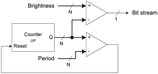
Since this signal is periodic, its amplitude spectrum is a set of discrete frequency components with the highest one being at the fundamental frequency. This means that most of the electromagnetic interference (EMI) generated will be concentrated at this frequency.
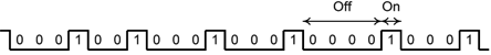
If we think about the PWM signal as a bit stream, then it is one with fixed frame length, which is the same as the period. Within the frame, all off-bits are grouped next to each other and all on-bits are grouped next to each other – see Figure 3.

Since on-bits are next to each other and off-bits are next to each other, it is the length of the frame, or period, that determines whether flicker is visible or not. This period has to be short enough to avoid flicker. It generally has to be shorter than 20 ms for the LED output to be above the human flicker fusion threshold, which is just a statistical and subjective limit.
To be conservative, it is desirable to limit the period to maximum 333 μs, which corresponds to a minimum frequency of 3 kHz. This is necessary because the eye can perceive high-frequency flicker when it moves. Since all information needs to be crammed into this 333 μs frame, a very high-frequency module clock is required for high brightness resolution.
For example, with 12- bit resolution, there are 4096 bits in each period for which a PWM module clock frequency of 12,288 MHz is required. For 16-bit resolution, the clock requirement is almost 200 MHz. Furthermore, taking videos of LED lights with non-high-end cameras may also cause flickering in the recorded footage.
The general recommendation is that the period should be maximum 100 μs which is an even more challenging requirement. However, there is currently no official standard.
Pulse-density modulation with variable quantisation
There is an alternative modulation method that overcomes the problems mentioned above. A first-order sigma-delta modulator (Figure 4) can also convert the brightness value into an on-off signal. It generates a pulse-density modulated (PDM) bit stream which has an inherently high rate of switching.
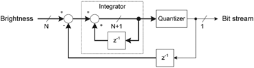
This modulation method is commonly used in sigma-delta analog-to-digital converters, except that in this case low-pass filtering is performed by the human eye.
A PDM bit stream can also be organised into frames. Every frame contains 2N bits where N is the resolution. The bit stream has an inherently high rate of switching because on-bits and off-bits are spread uniformly within every frame. The number of on-bits in each frame depends on the input value.
Due to the quasi-random nature of the switching, there is no meaningful frequency or period. The spectrum is more spread than it would be with a fixed period, the components are at high frequencies due to the high rate of switching and their amplitude and distribution depends on the input brightness value. This significantly reduces if not eliminates most flickering problems.
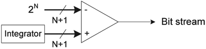
For even better EMI behaviour, the amplitude spectrum can be further spread by randomising the PDM bit stream. This is possible by slightly modifying the sigma-delta modulator setup by adding zero-mean noise to the quantiser. Normally the 1-bit quantiser acts as a comparator with a compare value of 2N – see Figure 5.
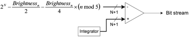
By varying the input compare level as a periodic function of the input brightness level (Figure 6), the randomness of the output can be increased and its amplitude spectrum spread. If the mean compare level is the same as the original compare level of the quantiser, then the mean value of the output bit stream is unaffected.
Additionally, due to having multiple transitions within each frame, the module clock frequency requirement is much lower for the same flicker-free experience than with pulse-width modulation. For example, at 25% brightness level, the longest time without a transition in a 12-bit system is only four bit times. Even with a module clock as low as 200 kHz, this takes only 20 μs.
Flicker may however still occur at very high or very low brightness levels when there are only a handful of transitions in every frame. Flicker at low brightness may be more critical due to the human eye’s high sensitivity to changes at low illumination.
The solution to this problem is the flicker watchdog. It is a simple circuit that limits the maximum number of consecutive off-bits (on-bits) by inserting an on-bit (off-bit) when the limit is reached and resetting the sigma-delta modulator. This limit can be user-selectable to adjust to any application. Naturally, using the flicker watchdog restricts the minimum non-zero brightness.
Another potential requirement is minimum stable times without transitions. Many linear or switch-mode LED drivers, especially the ones designed for high-power lamps, require their enable input to be stable for a certain minimum time. For example, a BCR450 LED driver IC from Infineon requires the on-time of the input signal at its enable input to be at least 10 μs.
To fulfil this requirement without changing basic system properties, the bit stream may need to be slightly reorganised. Some on-bits may need to be grouped next to some other on-bits and some off-bits may need to be grouped next to some other off-bits, if available. The number of similar bits to be grouped together depends on the LED driver used and has to be user-selectable.
This can be done by a packer circuit (Figure 8) that continuously counts the on-bits and off-bits of the bit stream, and generates an equivalent bit stream where the bits are grouped. Reorganising the bits has no effect on the mean value of the output bit stream.

Dynamic control
If modulation works as desired, it converts the brightness value into an on-off signal that controls the LEDs in such a way that their average luminous intensity is directly proportional to the brightness value itself and the modulation is imperceptible to the human eye.
Once this is achieved, the second big task is controlling the dynamic behaviour of the brightness value over time in a way that appears natural and is comfortable to the human eye. Assuming that the LEDs are organised into multiple channels, dynamic change can be divided into two distinct transitions. One is overall brightness change, also known as dimming. The other is colour change, a change in relative intensities.
Dimming
During dimming, all channels change their brightness level but their relative brightness remains the same, to preserve the colour of the multi-colour lamp. The human eye does not sense brightness linearly. There seems to be an approximately logarithmic relationship between physical luminance and perceived brightness (Weber-Fechner law) although the exact details are still debated.
If the brightness level changes linearly over time, the eye does not perceive the rate of change as constant. For the experience of smooth, gradual and constant change, dimming needs to be exponential. The ability to dim along an exponential curve is also a requirement by DALI, one of the most popular lighting communication standards.
DALI only defines 254 points of the exponential curve. A fixed time base is assumed whereby these 254 points are time equidistant. Dimming can be performed by having a periodic interrupt that changes the brightness level based on a lookup table, along the curve defined by the points. Immediate transition between these points may look like discrete steps, not smooth.
Engineers are encouraged to apply interpolation and define more points to make dimming (or fading as it is referred to in the DALI standard) smooth and natural-looking. If this is performed by a microcontroller, the more points are defined along the curve, the more frequently interrupts need to occur and the higher the CPU load will be.
An alternative solution is using an automatic dimming engine, a hardware module which performs all this without CPU load, as illustrated in Figure 9. Ideally the user only needs to select a target brightness level and a fade rate, and the dimming engine automatically adjusts the brightness level along an exponential curve. Since the dimming engine does not rely on interrupts, it can follow the curve much more closely without additional CPU load.

For maximum brightness resolution, essentially it is an incrementer/decrementer with a variable clock base. At lower brightness levels, the clock base has a lower frequency and it gradually increases as the brightness level increases. The fade rate can be adjusted by adding a pre-divider to the clock tree. To simplify exponential clock generation, the exponential curve can be constructed of several linear pieces, as shown in Figure 10.

The human eye is most sensitive to changes at the lower part of the exponential curve, where the brightness level is very low. At low fade rates, each individual step in brightness may be visible. The solution is adding dither to every individual transition (Figure 11). As long as the rate of change of the dither is above the flicker fusion threshold, the transition between discrete levels will appear smooth and gradual to the human eye.

Colour change
The three types of cone cells in the human retina have their peak sensitivity to photons at different wavelengths. In the human eye, these wavelengths approximately correspond to red, green and blue. Colour experience depends on how much these cells are stimulated relative to each other.
It is common to build multi-colour lamps by combining three or more types of LEDs, each with a different dominant wavelength. It is then the relative brightness of these LED types, or channels, that determine what colour a human observer sees.
Many different colour spaces and representations exist but discussing them is not within the scope of this articles. The focus is on the RGB colour space and similar orthogonal models where each colour component can be directly expressed by the brightness level of an LED channel in the multi-colour lamp. Among other representations, the DALI standard also defines the ‘RGBWAF’ colour type in which up to six different LED channels define the lamp colour.
It is often desired that the lamp colour change smoothly and gradually as this appears more aesthetically pleasing than abrupt colour changes. This article proposes a new method for this, called the linear colour walk. Similar to automatic dimming, the intention is to enable the user to set a target colour, start the transition and the original colour should change to the target smoothly.
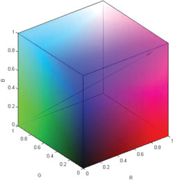
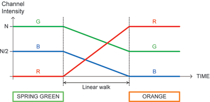
The ‘walk’ is along a straight line in the RGB colour space, represented by Figure 12. This can be achieved by changing the brightness levels of every LED channel simultaneously and linearly (Figure 13), making sure that all linear transitions take exactly the same time so that they reach their respective targets simultaneously.
The linear walker can be also realised as a decrementer/incrementer with a variable clock base. The clock frequency is derived from the difference between the original brightness and the target brightness, and the desired transition time. A fractional divider is needed in the clock generator for full control over the time the linear walk takes. It can be realised as a simple but effective quasi-fractional divider which is made of a bit-reversed counter and a comparator – see Figure 14.
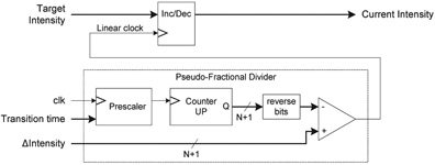
The generated clock has the desired average frequency but varying period time and duty cycle. This slightly decreases the linearity of very small brightness changes where linearity is not very critical due to the heavy quantisation effect that is present anyway.
Intelligent multi-channel lamp control architecture
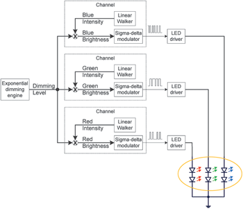
This article proposes a multi-channel architecture to generate the appropriate control signals for multi-channel lamps. Every channel generates one bit stream that determines the brightness of one physical lamp channel. The bit stream is generated from a channel brightness value by a modified sigma-delta modulator followed by a flicker watchdog and a packer.
The bit stream forms a modified PDM control signal. The channel brightness value is the product of the channel intensity and dimming level values to clearly separate overall lamp brightness and lamp colour. Channel intensity is generated by a linear walker. This value determines one colour component of the lamp and it can change linearly over time for smooth colour transitions.
Dimming level is generated by an exponential dimming engine. This value determines the overall brightness level of the lamp without affecting its colour. It can change exponentially over time which appears natural to the human eye. This solution is represented by Figure 15.
This proposed lamp control block is intended to be a part of a larger system that encompasses additional user functions such as communication and safety. Microcontrollers in Infineon’s industrial XMC1000 family contain a dedicated lighting module designed similarly to this solution.
For more information contact Davis Moodley, Infineon Technologies, +27 (0)11 706 6099, www.infineon.com
| Email: | [email protected] |
| www: | www.infineon.com |
| Articles: | More information and articles about Infineon Technologies |


© Technews Publishing (Pty) Ltd | All Rights Reserved
 printer friendly version