In recent years, the number of electronic loads using power supplies with rectifiers has risen in leaps and bounds. The resulting extreme distortion of the AC line current by harmonics ultimately led to the introduction of European standard EN 61000-3-2. EPCOS shows how its power factor correction (PFC) chokes make compliance easy and inexpensive.
Many electronic loads no longer draw their input current straight from the AC line in sinusoidal form, but via power supplies with rectifiers as high pulses of short duration. After the rectifier, the DC is smoothed by a storage capacitor (Figure 1). A transistor, a switch-mode power supply or other circuits then regulate the energy requirement of the electronic circuitry.

The zero crossing of the AC voltage and the low momentary values around it are therefore buffered by a capacitor, which in turn, only recharges during a relatively short time around the peak voltage (current conduction angle). A high current flows from the AC line only during this short period. These nonlinear current curves may also be regarded as the sum of an infinite series of sinusoidal harmonics whose frequencies are integral multiples of the fundamental. Despite the name harmonics, they generate all kinds of distortion in the AC line.
The problem lies in the high current pulses of short duration, which occur at the same time around the maximum line voltage for all power supply equipment connected. The current peaks cause the line voltage curve to deviate from its sinusoidal characteristic at the line impedance. The storage capacitor discharges its energy to the following circuit, so that the voltage across it drops and a charging current flows only when the line voltage VR exceeds the capacitor voltage VC. The duration of current flow (the conduction angle q) and the magnitude of the current peak depend on the discharge from the capacitor (capacitance of electrolytic capacitor C), the load circuit and the latter's line-side impedances. The load current obviously deviates from its ideal sinusoidal characteristic and thus produces considerable distortion. The current pulse can be calculated with Fourier's theorem as the superposition of sinusoidal oscillations whose frequencies are integral multiples of the fundamental (50 Hz), ie harmonics (100, 150 Hz, etc.).
Line pollution has various effects on the AC line and other low-voltage loads. In control and communication equipment, malfunctions may result from harmonic currents on the neutral and ground conductors and from distortion of the (sinusoidal) line voltage. Power is also dissipated as a result of reactive currents in transformers, motors, leads, chokes and capacitors.
Manufacturers have two options for limiting harmonics in their equipment. They can insert chokes in the power leads (passive solution) or use an electronic power factor controller (PFC) to generate an approximately sinusoidal line current (active solution).
Measuring input current harmonics with various capacitors
In a typical circuit (Figure 1), guide values were determined for the harmonics as a function of input power by varying both the capacitance of the storage capacitor and the load. The harmonics of the fifth and seventh orders increase with capacitance. The current curve reaches higher peak values, ie is steeper, whereas the current conduction angle becomes smaller (Figure 2).

Requirements of standard EN 61000-3-2
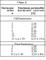
EN 61000-3-2 belongs to the EMC standards (specifically generic standard EN 50081 on emissions) and comes under the EMC guidelines and thus CE conformity marking of electrical equipment. Since 1 January 2001, all equipment placed on the market in Europe, and not only new products, must conform to this standard. The industry was slow to grasp its implications and did not raise an outcry until after the standard had come into force. A clarification (A14) added in 2000 that managed to settle the most doubtful points by 1 January 2001, so that manufacturers are certain of the legal position. The following equipment classes and associated harmonic limits were introduced under EN 61000-3-2/A14:10/2000:

Class A: Symmetrical three-phase equipment, domestic appliances (except those included in Class D), electric power tools (except portable tools), dimmers for incandescent lamps, audio equipment, and all equipment not covered by the other classes.
Class B: Portable electric power tools (Class A values multiplied by 1.5).
Class C: Lighting equipment.

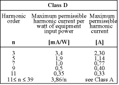
Class D: Personal computers and monitors, TV receivers and radio receivers with an input power of 600 W or less.

The limit curve calculated for the third harmonic (3,4 mA/W) in a class D device is shown in (Figure 2). Reduction of the third harmonic presents the greatest challenge to the supplementary circuit, as the higher harmonics are automatically attenuated more strongly.
Basically, there are two ways of reducing harmonics below the limits specified by EN 61000-3-2 by means of a PFC circuit: the passive solution and the active solution. In the passive solution, a storage component (inductor) is connected. The active solution makes use of an electronic control circuit (controlled rectifier or boost converter).
In the passive solution, the choke connected before the bridge rectifier buffers energy from the AC line and flattens the steep current pulses. The choke can easily be retrofitted. This method also has the advantage of high efficiency (98 to 99%). For higher power classes, especially in single-phase equipment, the choke becomes very large, heavy and space-consuming. In the active solution, the input capacitor can be decoupled from the AC line by a boost converter, allowing the input current to be electronically regulated. Component costs and space requirements (cooling of the semiconductors) are higher than for the choke solution.
Both solutions involve additional expenditure, which depends on equipment specifics as well as on cost criteria. It must also be remembered that harmonics fluctuate considerably with equipment current consumption.
In a fixed circuit, standby, half-load or full-load operation results in different input current consumption and different current curves. The effectiveness of the PFC circuit then depends significantly on the dynamic response, ie the inductor must be operated at the right level in the proportional range and becomes ineffective if the core goes into saturation.
In the first measurement (Figure 3 left, without additional PFC circuit), the current of the third harmonic greatly exceeded its limit value. Where the 100 µF electrolytic capacitor was used, an 18 mH choke with a powder core (Figure 3 centre) was initially connected, followed by a second choke (Figure 3 right). It became apparent that the harmonics cannot be reduced below the limit values until a choke with an inductance greater than 36 mH is used. As a general rule, an inductance greater than 40 mH, which can be split between two coils for live and neutral, must be specified to reduce the third harmonic in the current curve.

Summary
In force since 1 January 2001, European standard EN 61000-3-2 defines harmonic limits for input power consumption in various equipment classes. Passive power factor correction (PFC) is the easiest and most economical way of complying with this standard.
| Tel: | +27 11 458 9000 |
| Email: | [email protected] |
| www: | www.electrocomp.co.za |
| Articles: | More information and articles about Electrocomp |
© Technews Publishing (Pty) Ltd | All Rights Reserved