


HumiSeal has carried out significant technical service work in its laboratories on behalf of a major Tier 1 automotive supplier to address the application issues that arose during qualification with HumiSeal UV40, and to optimise application parameters of the Asymtek selective coating.
The particular areas that were focused on were optimising cycle times and the amount of material applied, and agreeing the optimal curing of these materials. This article outlines what was involved.
In Europe, many of the automotive electronic suppliers use Asymtek selective coating equipment, together with solvent-based materials. The non-atomised film-coater technology in particular, is extremely prevalent and, as existing equipment, the goal has always been to formulate a VOC free drop-in replacement for the solvent-based materials.
The Asymtek film-coater was designed to provide non-atomised, selective application of conformal coating materials with viscosities of less than 100 centipoise (cPs). This technology is ideal for use with solvent-containing materials and generates a leaf-like fan pattern ensuring accuracy and edge definition, as well as delivering fast coating cycle times.
With some solvent-based coatings using as much as 80% solvent to achieve a useable viscosity under 100 cPs, wet film thicknesses are generally high (200–300 μm) to deliver a dry-film thickness that meets the IPC requirements of 30–130 μm. In addition, VOC emissions are generally high due to the large solvent content; this is becoming more and more relevant in the European market place.
However, with 100% solids materials, whatever wet thickness is applied is converted into a similar dry-film thickness, and this has proved to be the problem with 100% solids material, both from a cost (the materials are inherently more expensive due to higher solids content) and material performance point of view.
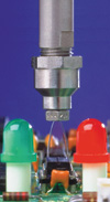
The SC-300 tri-modal applicator is designed for use with solventless coatings, thereby supporting environmentally responsible practices. The SC-300 applicator is easy to maintain and offers several key features to make ownership simple. The zero-cavity nozzle tip prevents material build-up during operation and allows for cleaning without disassembly; there are minimum wetted parts to replace or clean; the use of advanced materials and smooth internal surfaces also makes them much easier to clean.
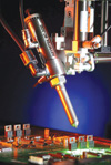
For a broader selection of spray patterns, one of three airflow extensions can be fitted onto the main assembly. The airflow extensions along with the three spray modes provide coating patterns to fit the application. The high flow rate produces film builds quickly, while allowing for fine control while the fluid passage provides uniform fluid flow distribution. The air and fluid chamber are co-located so that there is rapid response to changes in operation – there are no long air lines to delay response or to fail.
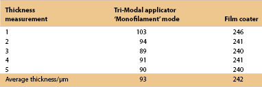
Material consumption
By comparing the average thickness of stripes applied by both film-coater and trimodal applicator applied on a flat-metal panel and using an eddy-current thickness measurement device, it is easy to see (Table 1) that material consumption with the tri-modal applicator is likely to be just 40% of that used with the film-coater.
Material performance
It must not be forgotten that low viscosity fluids are more prone to capillary flow than higher viscosity materials and this can lead to ‘super-thick’ localised areas, especially around IC component leads and around discrete components.
These localised ‘super-thick’ spots clearly exacerbate any material tendency to crack during thermal shock exposures, thus tri-modal application enables a thinner, more even and homogeneous film to be applied. This results in a considerable increase in the number of thermal shock cycles that the coating will survive.
In order to demonstrate this to be the case, 16 boards were coated using a film-coater. Various trial formulations were prepared at 75 cPs (ranging in modulus from 1207 MPa to 1451 MPa at -40°C) and subjected to thermal shock testing between -40°C and +125°C using the exposures shown in Figure 3.
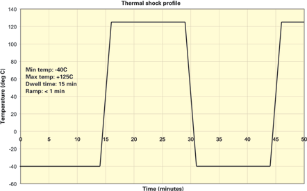
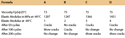
Simultaneously, a further 16 production boards were coated using the tri-modal applicator and various trial formulations prepared at 250 cPs (UV40 at 500 cPs), again ranging in modulus from 1290 MPa to 1492 MPa and subjected to the same thermal exposures. The results are shown in Table 2.
Boards were inspected for coating cracking using 40X magnification at the intervals indicated in the tables.
So it seems clear that elastic modulus (sometimes referred to as Young’s modulus) is much less important than the thickness and homogeneity of the film, in surviving thermal shock exposures.
Cycle time
Due to the high-volume production environment of the Tier 1 automotive manufacturer, there was concern that because the tri-modal applicator runs at only 150 mm/sec as opposed to the velocity of the film-coater applicator at 350–400 mm/sec, that the cycle time would be more than twice as long.
While this may be true for extremely simple boards, as soon as the boards become slightly complicated, the cycle times become similar, because the tri-modal applicator can apply wider stripes and there is no need to rotate the applicator to change coating direction.
In fact, for the boards coated in this study, the cycle times were exactly the same for both applicators, although since the zero-cavity tri-modal applicator needed less cleaning than the film-coater applicator, it could be argued that the cycle time was in fact shorter and the process more robust.
Curing
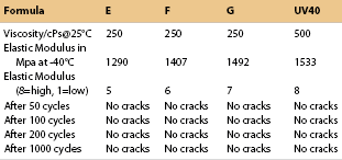
Dose and irradiance are key concepts when curing UV coatings that are too often mixed up. Those concepts are different but closely related together and defined in Figure 4.
UV irradiance (mW/cm²) is the power or the intensity of the UV energy which is delivered to a surface per unit area. It is a characteristic of the lamp and geometry of the reflector and does not vary with the speed. The intense focused peak directed under the lamp is referred to as ‘peak irradiance’.
UV dose (mJ/cm²) is the total energy delivered to a surface per unit area, passed under a UV light source. It is inversely proportional to the speed under the light source and proportional to the number of exposures or rows of lamps.
Energy is the product of power and time. A low irradiance for a long time does not give the same cure results as a higher irradiance for a proportionally shorter time, due to the differing kinetics of the curing reaction that takes place under the two conditions.
With the material targeting high-volume production, HumiSeal UV40 has been optimised for curing in an in-line, high-energy, conveyorised curing system.
Process control of a UV curing material
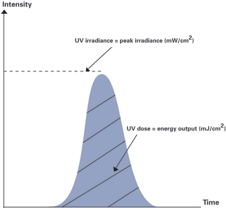
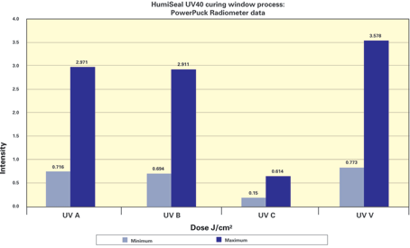
Controlling curing process window is easily quantifiable with a sensing system called a radiometer (Figure 5). This instrument measures the total UV dose and irradiance on four different channels (UV-A, UV-B, UV-C and UV-V) simultaneously, thus ensuring a repeatable and controlled curing process, while monitoring the output of the UV lamps.
The procedure is as simple and fast as passing the instrument through the tunnel and removing it at the end, while the radiometer is logging UV dose and energy.
UV40 will exhibit different responses to spectral distribution, dose and irradiance. Curing a coating without sufficient energy results in a sticky film; too much energy can result in residual stress, excess shrinkage and cracking.
Use of an inappropriate wavelength will give a softer film than when cured with the appropriate bulb type.
In Figure 5 is the curing process window (maximum and minimum UV dose) under which UV40 cures to a tack-free stage and provides sufficient hardness to enable the boards to be handled.
The conveyor speed can vary between 1 m/min and 3 m/min depending on height of lamp, power output of the lamp, shape of the reflector, height of components etc.
Trying to increase production throughput by increasing the intensity of light while decreasing the duration of exposure may not always be successful, since it must be ensured that sufficient UV dose has been applied to the coating.
It is extremely important to cure a UV coating within the recommended process window in order to obtain maximum reliability and performance of the coating. It is therefore essential to choose correct UV curing equipment that will enable one to work within this process window.
Conclusion
The use of tri-modal, air assisted spray coating is the way forward with UV40 as it enables the application of thinner, more homogeneously applied UV40 films, resulting in reduced material consumption and increased levels of coating protection, especially during thermal shock excursions.
Given the ability to apply wider stripes using air assisted technology, fewer stripes are required to coat a unit area, and that it is not necessary to rotate the applicator to change coating direction, on more complex boards, the tri-modal applicator can deliver similar cycle times to the more familiar airless film-coater style applicators.
Finally, it is important to understand the cure requirements of UV40 and to select equipment that can deliver an appropriate dose of the required wavelengths to meet the cure process window. It is also important to monitor the output of lamps periodically to ensure no degradation with time and to ensure consistency of production. One can think of it as profiling a reflow oven.
| Tel: | +27 11 865 4141 |
| Email: | [email protected] |
| www: | www.afrisol.co.za |
| Articles: | More information and articles about Afrisol |


© Technews Publishing (Pty) Ltd | All Rights Reserved
 printer friendly version