


Designing radio frequency (RF) remote controls has never been easier thanks to the advent of highly-integrated, single-chip RF solutions. System-on-chip (SoC) transmitter solutions greatly simplify the process of designing a remote control and reduce system bill of materials (BOM) cost by eliminating the need for numerous discrete components.
Remote controls come in many different sizes, shapes and wireless technologies, and are widely used in the consumer market as accessories for a wide range of products, such as televisions, video games, stereo systems, lighting controls and home automation including garage door/gate openers, air conditioning units, fans and automobiles with remote keyless entry (RKE) key fobs. The most common remote controls use infrared (IR) technology because of the relatively low cost of IR components, but these IR-based controls suffer from many drawbacks including requiring line-of-sight, limited operating angles, short transmission range, reflection problems and high current consumption associated with the IR LEDs, which leads to low battery life. RF remote controls resolve these issues and are appearing in greater numbers because consumers are demanding a much better user experience. In addition, technology improvements are closing the RF-IR price gap.
All RF remote controls share common features as shown in the simplified block diagram in Figure 1. The basic components of an RF remote control are buttons for the user to input a command, a microcontroller unit (MCU) to process the user commands into digital messages, an RF transmitter (RF Tx) to modulate and transmit the message, an antenna and a battery to provide power to the remote control.

The common challenges manufacturers face in designing RF remote controls are to provide consistent maximum transmission range, ensure long battery life and maintain low system costs. Maximising transmission range involves transmitting as much power as possible (within governmental regulatory limits) while providing a receiver with excellent sensitivity, since the total transmit distance is a function of both the transmitter output power and the sensitivity of the receiver.
From the remote control side, the design goal is to set the RF output power to the government limit, which implies that all remote controls should have the same output performance, since they all transmit within the same limits. This would be true in an ideal world, but, in the real world with real components and manufacturing tolerances, it is practically impossible to transmit at this optimum power every time with every remote control manufactured on the production line. Moreover, interference from a user’s hand holding the remote control or even touching a button (known as the ‘hand effect’) changes the impedance of the antenna and thus changes the transmit output power. This real-world effect can reduce the effective radiated power (ERP) of a remote control and easily result in output power 6 dB below the government limit, with a corresponding 2x reduction in transmit distance per Friis’s free space path loss equation.
These effects can be alleviated to maximise transmitter antenna efficiency by adjusting an on-chip variable capacitor to resonate with the inductance of the antenna. These automatic capacitor adjustments maximise the transmit power of the remote control by compensating for mismatches in the antenna matching circuitry and reduce design cost by relaxing manufacturing tolerances in the PCB antenna. For example, the Si4010 transmitter, the latest member of Silicon Labs’ EZRadio line of wireless products, is said to be the industry’s first single-chip remote control IC, requiring only one external bypass capacitor, a printed circuit board (PCB), battery and an external casing with pushbuttons to form a complete remote control. The Si4010 includes a patented antenna tuning circuit that automatically fine-tunes the antenna for optimum transmit power on every button press.
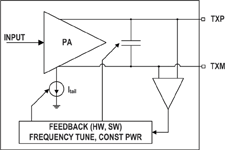
With standard remote control designs, variations in the RF transmitter, component and antenna manufacturing tolerances and the environment can lead to large antenna inefficiencies and wasted power. Figure 2 shows a simplified block diagram of the Si4010’s power amplifier and antenna tuning circuitry. An additional feedback loop is incorporated into the power amplifier (PA) to maintain constant output power by monitoring the voltage at the output of the PA and adjusting the PA’s current drive to compensate for changes in the antenna impedance. This feedback loop works to maintain constant output power in spite of temperature variations and the hand effect. The net result of antenna tuning is to provide consistently reliable and optimal performance on every button press while reducing the cost and design complexity of the RF matching requirements. Remote controls designed with the Si4010’s automatic antenna tuning feature can reliably and consistently operate at the government transmit limit for maximum transmit range.
Battery life is an important consideration for any portable electronic device, especially a remote control. When we consider typical remote control usage, more than 99% of the time, a remote control is waiting for a user to activate a button press. During this time, the Si4010 consumes less than 10 nA at room temperature, making it an ideal choice for battery-powered applications. Additionally, wake-on-touch GPIOs further minimise current consumption of the remote control and extend battery life.
During transmission, the Si4010 consumes either 14,2 mA in on-off keying (OOK) mode or 19,8 mA in frequency-shift keying (FSK) mode while transmitting at +10 dBm output power. If we assume that the transmitter transmits at a data rate of 1 KBaud, the data is Manchester encoded and each packet is 100 bits long and repeats three times for each button press, then we have the following results: At 50 button presses per day for five consecutive years, we use only 52% of the charge in a 220 mAhr CR2032 battery in OOK mode and 71% of the charge in FSK mode. Although this example does not include the self leakage of the battery, it does illustrate the low-power characteristics of the Si4010 transmitter and the importance of low standby current.
One of the most important considerations in any remote control design is minimising total system design cost, which is influenced by many factors besides component costs, including labour, inventory, test and manufacturing yield. By far, the dominant low-cost RF remote control solution on the market today uses an MCU and a surface acoustic wave (SAW)-based RF transmitter as shown in Figure 3.
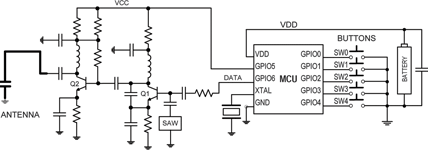
The wide acceptance of this design topology stems primarily from its low cost and simplicity. A SAW device is resonated with transistor Q1 in a Colpitts oscillator structure to form the carrier frequency, while transistor Q2 provides the output power amplification and isolation needed for stable operation. Data from the MCU is applied directly to the SAW resonator to form the OOK modulated signal, and GPIO6 from the MCU supplies the voltage (VCC) to the SAW-based transmitter.
This entire solution uses 24 external components, including the MCU, one bypass capacitor, a quartz crystal used to clock the MCU, and a PCB with a trace antenna and capacitor. In US currency, it has an RF component cost (excluding the PCB, MCU and bypass capacitor) of $0,77 USD in 100 000-unit volumes. The $0,77 RF BOM cost does not include the cost of the MCU, bypass capacitor or PCB. Traditionally, this has been the lowest component cost solution available for reliable RF transmission. From a system cost perspective, the large BOM count increases other costs, such as labour, inventory and tests, and reduces manufacturing yield.
Although SAW-based transmitters are widely used in remote controls because of their low component costs, there are many disadvantages with this old technology. Besides the high system cost from the large number of RF BOM components, SAW-based transmitters also suffer from poor carrier frequency accuracy, single frequency operation, OOK only modulation, inconsistent performance, sensitivity to component tolerances and low manufacturing yield.
In contrast, the Si4010 transmitter is a complete system-on-chip (SoC) remote control IC. Based on the proven Si500 silicon oscillator, its patented crystal-less architecture achieves ±150 ppm carrier frequency accuracy over the commercial temperature range and ±250 ppm over the industrial temperature range, which is twice as accurate as traditional low-cost SAW-based transmitters with no external crystal. The device operates over a continuous frequency range of 27 to 960 MHz and includes a programmable power amplifier (PA) with output power of up to +10 dBm, automatic antenna tuning and PA edge rate control to comply with FCC, ETSI and ARIB radio frequency regulations.
The embedded 8051 MCU is instruction-optimised for fast throughput and comes with 512 Bytes of internal data RAM, 4 KB of RAM, 8 KB of OTP NVM, 128 bits of EEPROM, a 12 KB library of ROM functions and a hardware-accelerated, 128-bit AES encryption algorithm. The device’s 1,8 to 3,6 V supply range, low standby current of less than 10 nA and wake-on-touch operation make the Si4010 ideal for coin-cell battery applications. Figure 4 shows a block diagram of the Si4010 transmitter SoC.
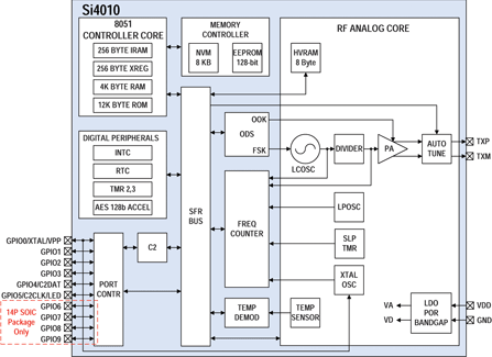
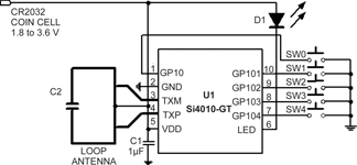
Figure 5 shows a remote control schematic using the Si4010 with an optional LED to indicate when a button is pushed. The total BOM components for this remote control (excluding the optional LED) are a single Si4010 IC, one bypass capacitor, and a PCB with a PCB trace antenna and capacitor. Not only are the total BOM components of the Si4010 much less than the SAW-based transmitter (3 compared to 24), the Si4010 also does not require any RF components because they are all integrated within the IC. Furthermore, the device’s automatic antenna tuning feature guarantees consistently reliable output power and reduces costs by enabling the use of relaxed tolerance manufacturing processes since high accuracy antenna matching is no longer required.
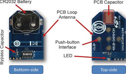
Designing a remote control using the Si4010 overcomes many issues commonly found with traditional RF transmitters. The hardware task comes down to choosing the best PCB antenna for the given remote control geometry and laying out the pads and connections for the Si4010, the PCB trace antenna, a bypass capacitor, buttons and the battery. Figure 6 shows the PCB of a Si4010 remote control for 434 MHz operation.
Developing a remote control application is simplified by using the Si4010 transmitter’s library of remote control functions stored in its 12 KB ROM. The library includes button service routines, AES encryption, encoding modules, battery voltage measurement and other useful remote control functions to reduce code size and speed time-to-market.
Figure 7 shows a flow diagram of the Si4010 used in a remote control application. Upon battery insertion or waking up from standby mode from a button push, the Si4010 automatically begins the boot process of copying user code from the non-volatile memory (NVM) to the RAM, followed by the running of user code. After booting, the digital blocks of the device are first initialised (the MCU, interrupts, timers, peripherals, etc), and then the analog blocks are initialised with functions found in the ROM library. For example, the modulation type (OOK or FSK), data rate, PA transmit level, carrier frequency and so on are set during this phase.
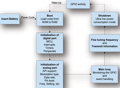
When initialisation is complete, the program enters the main loop where it monitors the GPIOs for button presses and manages event handling. Depending upon which button is pushed, the program decides what to do and then assembles the appropriate packet according to the button press. Then, the Si4010 fine tunes the frequency and transmits the packet. As soon as the information is transmitted, it shuts down and returns to the ultra-low-power standby state. In standby mode, the chip consumes less than 10 nA at 25°C and can wake up from any GPIO button press to begin the process again.
For more information contact Gary de Klerk, NuVision Electronics, +27 (0)11 894 8214, [email protected], www.nuvisionelec.co.za
| Tel: | +27 11 608 0144 |
| Email: | [email protected] |
| www: | www.nuvisionelec.com |
| Articles: | More information and articles about NuVision Electronics |


© Technews Publishing (Pty) Ltd | All Rights Reserved
 printer friendly version