


System management means, fundamentally, that all functions that are necessary for the reliable operation of the system are detected and remotely monitored.
Should a function fail, the system management ensures that the failure is recognised, to minimise any disruption to overall system functioning. This article gives an overview of the topic of system management for electronics packaging systems based on AdvancedTCA, MicroTCA, CompactPCI and VMEbus.
But first, a brief definition of terms: the term for overall management in electronics packaging systems is ‘system management’. This covers all the units, starting with the controllers on the plug-in PCBs, up through the transfer protocol, to the overall system administrator. For management at subrack level (shelf or chassis), the term ‘shelf management’ or ‘shelf manager’ will be used in this article. The logical unit that sits on the shelf manager is termed in the IPMI specification the BMC (baseboard management controller). The shelf manager reports to the ‘system manager’, which is a superordinated unit that monitors a number of shelves, similar to a head office. In the system specifications, the system manager is not prescribed in detail and its mode of implementation is not fixed.
Standards
Shelf management in electronics packaging systems is based, for practical purposes, exclusively on IPMI. This stands for ‘intelligent platform management interface’ and is a standardised, non-proprietary interface that was originally intended for servers and which monitors physical quantities such as temperatures, voltages, fan speeds and power supply points. The IPMI specification was developed in collaboration with Intel, Dell, Hewlett-Packard and NEC and issued in 1998, with numerous additions since. Since the same parameters apply in electronics packaging as apply to commercial servers, and again system components are used from a large range of suppliers, IPMI was also accepted as the standard for embedded systems. IPMI defines the IPMB (intelligent platform management bus) as the data link between the modules.
On backplanes and on the components of an embedded system, the IPMB is physically implemented on the I²C bus which is a serial two-wire bus with clock (SCL) and data line (SDA). The data rate is typically 100 Kbps, which for system monitoring purposes is entirely sufficient.
Tasks of shelf management
The principal task of the shelf management is to ensure that all vital functions of the system are monitored, that alarms are signalled in the event of a failure and that countermeasures can be taken. Below is an overview of the most important tasks of shelf management in the system. Implementation may differ between specifications (AdvancedTCA, MicroTCA, CompactPCI, VME).
Temperature monitoring
The shelf manager monitors all temperature sensors in the system and can thus respond immediately if a board overheats. It responds in such a case first by increasing the fan speed; if this is not sufficient and the temperature reaches a critical threshold, the shelf manager can disable the board completely, thus preventing further damage (eg, fire).
Electronic keying/hot swap
Essentially, keying means that a plug-in board can only be activated if it meets the requirements of the slot into which it is to be inserted. Traditionally, such requirements have been mechanically coded in terms of elements on board and slot that function as keys. If the key elements match, the board can be inserted into the slot.
Electronic keying, however, means that while the board can be physically inserted into the slot, it can only be activated by the shelf manager. The shelf manager further checks whether the slot is capable of delivering sufficient electrical power and/or cooling for the board. In systems such as AdvancedTCA, in which different backplane interfaces may be found, the shelf manager checks whether the board is compatible with the backplane interface. The relevant data, eg, power requirement, interface type, etc, are stored in EEPROMs on the board and in the system and are read by the shelf manager.
Fan control/fan failure monitoring
The power requirements of electronics packaging systems continue to increase steadily. It is not uncommon for a system the size of a cube with a side length of half a metre to dissipate up to 4 kW of electrical power as heat. To transport this heat out of the system requires very powerful fans. Since these fans themselves consume large amounts of energy and make considerable noise, it is important to control them such that they only run as fast as is required at a given time.
Regulations govern the maximum permissible noise generated by the system for various operating environments.
Typical regulations include NEBS (Network Equipment Building Practice) and ETSI (European Telecommunications Standards Institute). These distinguish between environments in which people work alongside the equipment, and those such as a computer centre, where human exposure is soley for maintenance purposes.
The shelf manager must ensure that the fans operate below the relevant noise limit while also providing sufficient cooling for the electronic components. A cooling algorithm used in Schroff’s AdvancedTCA systems makes use of the alarm thresholds of the IPMI temperature sensors. If all temperature sensors are in the ‘green zone’ – that is, no temperature thresholds have been reached – the shelf manager sets the fans to their minimum speed and thus lowest noise. When demands on the system are such that the upper non-critical threshold is exceeded, the shelf manager increases the fan speed in increments until cooling is sufficient that the temperature falls back below the upper non-critical threshold. The system is thus maintained at the optimum operating point in terms of cooling. In the event that the upper critical threshold is reached, all fans are set to maximum speed; should the upper non-recoverable threshold be reached, which could lead to component failure or fire, the entire affected component is disabled.
The shelf manager monitors the fans for failure. One particular type is based on what are known as adaptive thresholds. Here, signalling of a fan failure is not delayed until that failure is imminent, but rather is triggered at an earlier point. A reference speed is set for every speed step and an alarm threshold set relative to this, which might be, for example, 70% of the reference speed. Since it is rare for a fan to fail suddenly (most commonly it gradually loses speed as the bearings become worn), in this design imminent failure is signalled while the fan is in fact still delivering useful cooling.
Shelf event log (SEL)
A further important function of the shelf manager is to maintain a shelf event log (SEL). This stores all IPMI events such as exceeding or falling below thresholds, or the inserting or removing of components, in an events table. These tables can be used to trigger other actions or as an error diagnosis tool.
Power management
The shelf manager also monitors the distribution of electrical power in the system. The system power ratings – such as the total power available or that available per slot – are stored in memory, typically a serial EEPROM. Meanwhile every component in the system informs the shelf manager of the power it requires. The shelf manager compares this data and if there is sufficient power available for a board, the board can be powered up. This mechanism serves to protect a system’s power supply against overload.
Remote management
The shelf manager communicates via interfaces with a superordinated system manager. Typically, these interfaces are physically based on Ethernet. Protocols used include SNMP (Simple Network Management Protocol), used in networks for managing network components, and RMCP (Remote Management Control Protocol), that defines IPMI commands via Ethernet.
Shelf management is implemented in different ways by the various electronics packaging systems standards.
AdvancedTCA
With the PICMG standard 3.0 (AdvancedTCA) an open standard of micro computer packaging was published for the first time, which describes as a fixed part the management functions on the chassis. On approximately 130 pages, all aspects of this shelf management are described in detail and reference is made to further standards.
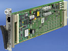
Priority was given in creating this standard on nominating the main features which are necessary for the interoperability of the chassis components. The real, physical implementation is left to the chassis manufacturers and the system integrators. The commonest implementation is one in which the shelf manager (Figure 1) is accommodated on a plug-in PCB that occupies its own slot in the system. In another type, the shelf manager is contained on both hub boards. Since the hub boards are in any case the ‘switching centre’ of the system, this is an elegant solution.
In addition to the shelf manager itself, every AdvancedTCA plug-in board features an IPMC (Intelligent Platform Management Controller). This device communicates with the shelf manager via IPMB and provides it with all relevant information on temperatures, voltages, fan speeds etc. If the AdvancedTCA PCB has plug-in AdvancedMCs (Advanced Mezzanine Cards), the controller is known as Carrier IPMC. This further assumes the task of creating connections to the AdvancedMC boards.
The IPMB is described in the logic as IPMB-0; physically, the commands are shared between two redundant buses, IPMB-A and IPMB-B. If one of the two buses should fail, in redundancy terms the other bus remains available. Chassis manufacturers offer two options for implementing IPMB-0 – the bussed IPMB-0 and the radial IPMB-0.
In the bussed version (Figure 2), the redundant IPMB signals of the shelf manager in the backplane are directed in a series to all AdvancedTCA slots. Should one of the redundant IPMBs fail (eg, because a faulty AdvancedTCA board shorts the bus lines to earth), the other IPMB remains fully available. The redundancy thus contains the failure event.

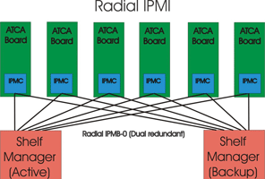
The radial IPMB (Figure 3) offers a higher degree of security. In this version there exists an individual (redundant) link between the shelf manager and each individual AdvancedTCA slot, in the manner of a star configuration. In the event of a connection failing, it can be isolated by the shelf manager, so that IPMB-A and IPMB-B remain available to all the other boards.
MicroTCA
In MicroTCA, a backplane was developed for the advanced mezzanine cards (AMCs) originally designed for AdvancedTCA carriers, resulting in a self-contained system. In MicroTCA two new modules were defined, the MicroTCA carrier hub (MCH) and the MicroTCA power module (PM), to carry out the functions performed in AdvancedTCA by the AdvancedMC carrier; both take the form of plug-in modules in the AdvancedMC format. MicroTCA also defines a further component at shelf level, the cooling unit (CU), which is responsible for heat extraction from the shelf.
The MicroTCA carrier hub (MCH) is the ‘management centre’ for all modules implemented and all AMCs. The MCH has the same form factor as an AMC. The MCH communicates with the AMCs via the radial IPMB-L that is connected between the MCH and the AMCs in a star configuration. The power module (PM) is the PSU and again has the form factor as an AMC. It accepts a variety of AC and DC input voltages and delivers 12 V d.c. for the AdvancedMC modules plus a separate 3,3 V d.c. for the management. The CU ensures the ventilation of the shelf. Normally this takes the form of a hot swap-capable fan module. The fan module is defined at shelf level but is controlled by the shelf manager via the carrier manager.
Management controllers
The management controllers sit on the modules in the MicroTCA shelf, connected to one another via the management buses, ie, IPMB-L or IPMB-0. These management controllers vary according to the module type.
The MicroTCA Carrier Management Controller (MCMC) is situated on the MCH and carries out the control function of the AdvancedMC modules, the power module and the cooling units via IPMB-L and IPMB-0. It receives information on the MicroTCA carrier via the I²C bus. The Module Management Controller (MMC) is situated on the AdvancedMC module and is linked to the MCH via IPMB-L. The EMMC is the Enhanced Module Management Controller for the cooling unit and the power module, and is connected via IPMB-0 to the MCH.
Figure 4 gives an overview of the relationships of the modules and management controllers. In this diagram modules such as MCH, CU and PM are not shown with redundancy implementation. To allow for redundancy, the MicroTCA specification provides for up to two MCHs, up to two CUs and up to four PMs. The position of the shelf manager can also vary with implementation; in this example it is outside the MicroTCA shelves. It could also be implemented, eg, on an AdvancedMC module or an MCH.

Shelf management hierarchy
The management controllers described here are physical units and have a fixed position on their respective modules. There is, additionally, the actual – logical – management hierarchy. On the lowest rung of this hierarchy is the carrier manager. This ensures that the AdvancedMC modules are activated and that only AdvancedMC modules with compatible software protocols are enabled. The carrier manager resides on the active MCH in the latter’s MCMC.
One hierarchical rung above this is the shelf manager, to which one or more carrier managers reports. It has no fixed place in the system. It is possible to implement the shelf manager on the MCH, but it can also be situated on an AdvancedMC module or outside the carrier. An important task for the shelf manager is control of the ventilation. Temperature sensors on all modules monitor the temperature constantly. If the alarm threshold on one of the modules is exceeded, the shelf manager receives a signal or ‘event’ via the carrier manager, and initiates an appropriate response, eg, an adjustment of the fan speed.
The top rung of the hierarchy is that of the system manager. This administers multiple MicroTCA shelves. The MicroTCA specification does not, however, go into detail concerning the implementation of the system manager.
CompactPCI
CompactPCI is specified in PICMG 2.0, released in 1995. This ‘core’ specification contains no detailed description of a shelf management. However, it reserved certain signal pins on the CompactPCI backplane connector that could be used for shelf management purposes, though without a description of the electrical signals or protocols. In 2000 the PICMG 2.9 specification was issued. This expands the PICMG 2.0 base specification by adding system management.
Like AdvancedTCA and MicroTCA, PICMG 2.9 uses IPMI as its base standard, and this also communicates physically via the I²C bus. Various methods exist for the physical implementation of system management in CompactPCI. Firstly, there are dedicated plug-in shelf manager boards, for which a special slot is reserved in the CompactPCI system. More economical on space is the option of integrating the shelf manager as a baseboard management controller (BMC) on the CPU blade. PICMG specifies two IPMBs, IPMB0 and IPMB1. IPMB0 is necessary and must be implemented, while IPMB1 is optional.
VME
When the VME specification was created in 1982, system management and function monitoring were still proprietary implementations of each manufacturer. The IPMI specification that appeared in 1998 was still a long way off. Since then, a working group has formed that is developing the implementation of a management system based on IPMI under VITA46.11 (System Management on VPX).
Prospects
Work is currently in progress on linking the hardware-side shelf manager level with the superior system manager level. The commands for operating the shelf manager are highly dependent on the hardware used. The aim is then to harmonise these commands ‘upwards’, ie, to abstract them, so that a system manager can communicate with a chassis without needing to know which chassis or shelf manager is being used. The so-called OpenHPI is used to provide this abstraction. OpenHPI is an open-source project from the Service Availability Forum (SA Forum) that provides the HPI (Hardware Platform Interface).
| Tel: | +27 11 608 3001 |
| Email: | [email protected] |
| www: | www.actum.co.za |
| Articles: | More information and articles about Actum Electronics |


© Technews Publishing (Pty) Ltd | All Rights Reserved
 printer friendly version