
A new class of Rogowski coil split-core current transducers: the RT series
The monitoring of electric power consumption has become a key element for managing electrical installations in industrial and commercial sectors, such as manufacturing facilities, data centres, food processing industries, retail outlets, hospitals or educational establishments. Three years ago, LEM introduced a system called Wi-LEM onto the market which is based on wireless sub-metering components, the EMN, enabling measurement of electricity segmented by activity (lighting, HVAC, motors, heating, etc). Initially the range seemed to be sufficiently comprehensive, with a metering capacity of up to 100 A. However, it was soon found to be too limited for the industrial or for the heavy-duty service domains and this was without taking into account the fact that monitoring often begins by measuring global consumption at the point of energy input – requiring a capability to measure up to 2000 A.
LEM therefore developed the RT current sensor adapted to these EMN devices, which provides the same flexibility of installation as split-core current transformers from the lower range, but with the same class 1 precision required for the sub-metering field. The Rogowski coil, which has long been noted for its ease of installation, offered the right solution provided that its major drawback could be overcome – that of inaccuracy caused by the sensitivity to the position of the conductor inside the loop.
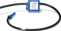
From theory to practice
A simple explanation of the Rogowski coil theory, is that it is a coil-winding that closes back on itself, wrapping the conductor to be measured like any toroidal-type current intensity transformer, the only – but major – difference being that there is no magnetic core. While Ampère’s theorem still applies, the equations are slightly different because at the sensor output we find that the voltage is in proportion, not to the primary current, but rather to its derivative: U = M*di/dt.
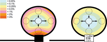
M is the mutual inductance between the primary conductor and the coil, which to some extent represents the coupling between the primary and secondary circuits. All the difficulty in obtaining good accuracy from this principle derives from the fact that the simplified analytical expression of this equation implicitly supposes perfect symmetry of the coil (M must be constant). However, this is never the case in practice, and this can be illustrated by looking at the three critical points that cause M to be variable.
* The density of the turns: the coil-winding must be perfectly regular to ensure that the winding density is uniform throughout. Turns that are not equidistant create asymmetry, the effect of which is to cause the coefficient M to vary according to the position of the primary conductor. This induces a de facto error resulting from the position of the cable or the busbar to be measured, an error which increases the closer the conductor is located to the area where the density differs from the average spread value.
* The coil cross-section: in the same way as the turns density, if the cross-section is not uniform all along the coil surrounding the conductor, term M will not be constant and an error is produced due to the positioning of the conductor. In this case too, the closer the conductor is located to a zone that significantly differs from the average spread value, the greater is the error.
* The coil clasp: a major advantage of the flexible Rogowski coil is that it provides an extremity with no electrical connection, the return signal being wired back inside the coil. Here is a major source of asymmetry caused by the discontinuity in the coil-winding which affects the turns density, when the theory requires that the coil should be perfectly continuous and homogeneous. This is by far the most critical point and generates the greatest errors.
The reality of the figures
Until now Rogowski coils have delivered at best a 2% positioning error. Added to this there are often restrictions which exclude the conductor from certain zones inside the loop, in particular at the closure of the clasp head. In reality this could even be quite catastrophic, resulting in errors close to the clasp head in the order of 6%. For this reason, it is easy to understand why manufacturers of energy metering equipment have always avoided employing this technology.
However, LEM recognised the viability of this technology for energy measurement, but it depended on whether they could manufacture coils which delivered a positioning error of less than 0,75% as a minimum. In fact, the objective of developing class 1 energy meters is to obtain an overall accuracy of better than 1% over the entire measurement chain, including the current sensor, the voltage sensor and the signal processing.
The challenge met by LEM
Multiple solutions based on electrical or mechanical concepts have been developed for nearly 100 years in order to resolve, albeit with very limited success, the main problem of the Rogowski coil current sensor, ie, the error caused by the imperfect sensor closure. Taking this into consideration, LEM engineers decided to revisit the theory in greater depth in order to better understand the reason for these unsuccessful attempts.
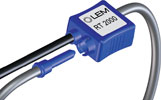
Thanks to the company’s expertise in magnetic, it was able to develop a very simple but effective solution – a sleeve made of magnetic material, making it possible to make an entire zone around the coil invisible (magnetically), and thus to mask the imperfections on the closing mechanism as well as the connections of the sensor’s secondary wires. The sleeve acts as a magnetic short-circuit (or more precisely a reluctance short-circuit), ‘virtually’ bringing together the two sections of the coil located on each side. This approach was a complete success – the error associated with the coil clasp became negligible. Naturally enough, the idea was the subject of a patent application in 2007.
The hidden challenge
While the major problem with the split-core Rogowski coil had finally been solved, other problems became apparent which diminished the success of the magnetic sleeve. The error associated with the design of the coil clasp system had previously been so important that it had, to some extent, masked the other causes of asymmetry. LEM continued to work to improve this current sensor and after a total of two years has been able to develop the processes and machinery that significantly reduce the symmetry faults, both with regard to the regularity of the coil winding and creating a uniform section over the entire length of the loop.
The results
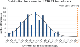
The graph in Figure 4 illustrates the improvements that LEM has been able to produce in the split-core Rogowski coil, compared with the level of accuracy of other products on the market that are based on this technology. Today the error due to the positioning of the conductor is specified at a maximum of 0,65% of the measured value for a 15 mm diameter conductor irrespective of where it is positioned, even if it is adjacent to the coil clasp. For a better appreciation of the results that have been obtained, Figure 5 shows the maximum value of the error over a sample of 210 RT Rogowski coils. Typical value of the error due to the positioning is 0,31% of the measurement for the new LEM sensor.

What one should also know about Rogowski coil sensors
External conductors
Performance of the Rogowski coil is generally expressed in terms of error associated with the positioning of the conductor to be measured, but a good sensor must also remain insensitive to all other external conductors located nearby. It happens that a relation exists between these two characteristics: a perfect loop is perfect for both, and a bad loop will be bad for both. This is a result of Ampère’s theorem, which states that any error associated with any form of asymmetry is valid both inside and outside the loop.
Consider, for example, a conductor on which a 100 A current is circulating, situated inside the Rogowski coil and which is in contact with a section of the loop inducing an error of +0,5%. A measurement of 100,5 A is therefore obtained. This same conductor at the contact of the same section, but outside the loop, will likewise cause an error of 0,5 A, but this is added to the current measured inside the loop which results from the principle of rejection of the external magnetic fields.
Absolute accuracy
In general, the absolute accuracy of Rogowski coil sensors is low because their gain (expressed by the term M) depends on physical parameters that are hard to control when it comes to mass production. To summarise, it is not realistic to try to manufacture this type of sensor with a gain dispersion of less than several percentage points (say between 2 and 5% depending on the technology used). This would mean designing coil-winding machines in which the pitch would be regulated to an accuracy in the order of microns, as well as being able to produce the coil-winding base with the same level of accuracy. It is therefore customary to connect the Rogowski coil to an active or passive electric circuit so that it can be calibrated, and a good absolute accuracy can be obtained.
On the other hand, it is essential to guarantee excellent stability of the sensor characteristics, in particular with regard to temperature, to prevent any drift from having to be corrected by recalibration to compensate for changed conditions during use. For example, LEM’s RT range has proved to perform very well in this respect at 30 ppm/°C.
No limit
It is a recurring issue when specifying measuring systems: will the sensor saturate if the current goes above its nominal value? Of course in the case of the Rogowski coil the answer to this is 'no' since it does not have a magnetic core, and as a result runs no risk of saturation. In theory, the limit of the current to be measured is infinite. In practice it is the diameter of the closed loop that establishes the nominal value of the current, not in relation to the measuring capacity, but rather in relation to the dimensions of the primary conductor. In the specific case of high di/dt (impulsion) the limit will be fixed by the voltage developed at the coil terminals instead.
Linearity
Of course, linearity is important when a sensor is intended for precision measurements. For the same reason that no saturation takes place on the Rogowski coil, it is not possible for there to be a lack of linearity, since the coil is intrinsically perfect in this respect. If differences were nevertheless observed, it would be necessary to question the measurement methods and not the Rogowski coil.
Phase shift
Phase shift is an extremely important parameter with respect to energy that is calculated from measurements of currents and of voltages. In the same way as for saturation and linearity, the Rogowski coil is perfect with regard to the phase – which means it induces no phase shift. However, it is worth bearing in mind that it is necessarily associated with an amplification stage (as described below under the heading ‘integrator’) which itself will generate a phase shift. In conclusion, the phase error is intrinsically zero when the coil is not connected, but it can reach high values as soon as a load is connected. However, this error can be easily quantified by calculation or by simulation of the equivalent RLC circuit, and compensated for by an ad hoc method.
The choices made by LEM
Today, the Rogowski coil sensors can compete against the best current intensity transformers in the energy measurement sector. It became very clear that LEM would need to exploit the properties of this technology to the maximum which could create a net benefit when measuring high currents, ie, the weight, overall dimensions, flexibility and manageability. With a cross-section measuring 5 mm, which could almost be classed as a ‘universal’ size, the sensors in the RT range are among the most slender Rogowski coil sensors on the market.
The patented coil clasp device is also small (28 x 30 x 16 mm), and provides a reliable connection of the loop to its coaxial signal cable. Here, the choice of a coaxial-type cable is directly associated with the low cross section of the coil. In fact, since the gain is proportional to the cross section, a fine coil develops little voltage, and it is appropriate to control the signal-to-noise ratio by starting to eliminate all risks of interference between the loop and the amplification stage.
Finally, to guarantee stability in time and temperature, the RT coil is moulded integrally into a PU resin, using an original process developed by LEM engineers. This wrapping technique also helps to maintain the different sections firmly and imparts a robustness to the assembly, as required for places where it is difficult to install.
Application note: design of an integrator for the Rogowski coil
The Rogowski coil supplies a voltage in proportion to the derivative of the primary current at its terminals. An electrical integrator circuit is therefore necessary to convert this signal into a signal that is proportional to the value of the primary current.
The integrator is an essential component in current measurement with the Rogowski coil, and the way this amplification stage is implemented will have a major impact on the sensor’s electrical performance (linearity, phase shift and frequency bandwidth). A list of the various critical aspects of such an integrator, with some possible solutions, is given below:
Very low signal level (for example 20 mV/kA for sensors in LEM’s RT range)
The use of very low-noise op-amps is recommended in this case to optimise the signal/noise ratio. It is necessary to try to minimise the surface of the PCB or possibly to shield the amplification stage to reduce sensitivity to external fields.
Low cut-off frequency
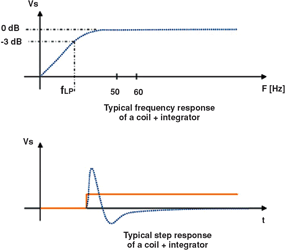
When an integrator is connected to a Rogowski coil, the two form a high-pass filter. Since it will reject very low frequencies, it is necessary to define the cut-off frequency in order to optimise performance at the nominal operating frequencies, while still obtaining the best possible response time.
Rejection of offset
The main problem of a pure integrator lies in the fact that it will integrate the slightest parasitic offset (eg, due to the op-amp), with the result that the output will always be unstable and will drift sooner or later to saturate at the upper or lower level. Consequently, it is essential to limit this drift, using a static gain or an active compensation stage, as shown in Figure 7.


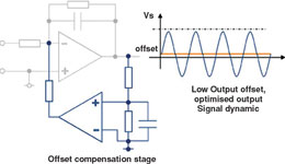
Total offset rejection
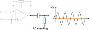
It is possible to completely eliminate the residual offset by adding a capacitive coupling device between the integrator and the measuring stage, as shown in Figure 8.
Phase shift
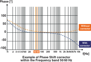
The offset rejection circuits described above will generate several degrees of phase error, which poses a major problem for the measurement of power. In this type of application, it is therefore necessary to add a phase-shift compensation stage, which generally consists of a low-pass filter. Unfortunately, the correction will not be constant, but will depend on the frequency, meaning it will be necessary to optimise the design to minimise the phase difference at the fundamental frequency, typically 16 2/3, 50, 60 or 400 Hz.

Calibration: active adjustment of gain
A Rogowski coil requires calibration against a reference signal in order to fine-tune its gain which is never exact by construction, due to inevitable imperfections in the manufacturing process. In general, engineers use the integrator stage to which an analog device, such as a potentiometer, is attached. The most recent digital calibration solutions are more likely to use a microcontroller or the combination of a microcontroller and a PGA (programmable gain amplifier). In all cases, calibration is specific to each individual Rogowski coil which must always use the same circuit with which it has been calibrated.
Calibration: passive adjustment of gain
Historically, the Rogowski coil was used simply for measurement of the current effective value (rms) without phase constraint. Many loops offered factory calibration based on a purely resistive or a resistive/capacitive circuit (RC circuit). While this method continues to be straightforward and economical, unfortunately it does not lend itself to power measurements due to the strong phase error that it generates, and its possible dependence on the frequency (if an RC circuit is used).
When developing the new Rogowski coils, LEM decided to offer a simple and generic product, keeping in mind that the integrator technology leads to the best performances and is a well known method. Therefore, the transducers of the RT family are not calibrated in the factory, do not use any additional electronic components or housings and do not require power supply. Using an integrator specific to the device connected to the Rogowski such as energy, power quality or pulse power monitor, has been deemed by LEM a cost-effective and high-performance solution.
| Tel: | +27 11 626 2023 |
| Email: | [email protected] |
| www: | www.denver-tech.co.za |
| Articles: | More information and articles about Denver Technical Products |
© Technews Publishing (Pty) Ltd | All Rights Reserved