More often than perhaps known, the outcome of a calibration procedure can depend on the technician knowing which cables and connectors are appropriate for the calibration setup.
Choosing the wrong cables and/or connectors can have a significant impact on the overall uncertainty of the setup or calibration system. For anyone new to DC and low-frequency AC calibration, it is important to understand the impact connectors and cables have on overall measurement uncertainty, as well as the importance of cable maintenance.
Cables, connectors and traceability
Because a calibrator must be electrically connected to the unit under test (UUT), there is at least one pair of connectors involved on both. These electrical cables or test leads bring the parameter represented by the calibrator to the UUT. In an ideal situation, the UUT would ‘see’ the standard value from the calibrator without any deterioration. Unfortunately, this is not always the case.
If a user fails to select the appropriate cables, the uncertainty chain can be violated because the cable-to-connector circuit may introduce serious errors into the signal that arrives at the UUT. In some cases, these errors may even be larger than the expected signal. So, to minimise the effect on ‘total uncertainty’, these possible error sources must be considered.
Model of a test connection
Figure 1 depicts a schematic diagram of a simple test setup including cabling and connectors. One can immediately see that there are many influences that might contribute uncertainty to the measurement system. Some of these influences are in series with the signal circuit, and others are in parallel.

Moving from left to right in the diagram, possible contributions to total measurement uncertainty are:
* Contact resistance between the connectors and cable junction at the calibrator.
* Thermal EMFs (voltages) generated at the connector and cable junctions at the calibrator.
* Series lead resistance in the cable wires.
* Series lead inductance in the cable wires.
* Parallel capacitance between the cable wires.
* Susceptibility to external electromagnetic interference (EMI) in the cables.
* Leakage resistance between the cable wires via their insulation resistance or external contamination.
* Thermal EMFs generated at the connector/ cable junctions at the UUT.
* Contact resistance between the connectors/cable junction at the UUT.
These possible error sources are present in DC, AC and RF measurements, but they affect each one differently.
Thermal voltages are a major problem in low-level DC voltage measurements. It is not unusual for connecting leads to binding posts to bring two dissimilar metals into contact with each other and thereby create a thermal junction. When this happens, the net thermal EMF generated induces a continuous current into the measurement system. That current can cause an error.
Looking at the four thermal junctions created in Figure 1, if one assumes that temperature is the same at all connections, the thermal voltages will be equal and opposite, thereby cancelling each other. If this is the case, then there is no contribution to error. Most often the temperatures at each binding post are identical, because they are very close together. However, if the calibrator’s binding posts are at a different temperature than the UUT’s binding posts, a net voltage difference may result in series with the calibrator and UUT, causing an error.
Whenever possible, it is best to use pure copper connectors and cables in a measurement setup to avoid uncertainties due to thermals. Or, if it is necessary to use other than pure copper against copper, it should be ensured that any junctions between dissimilar metals are at the same temperature. It is good calibration practice to try to do both as much as is practical, especially at low levels.
As an example, if a meter is going to be calibrated at 10 mV d.c., one should first check to see if there is any internal offset at the meter. To do this, the direct voltage source must be replaced with a copper short. If there is an offset, it can be eliminated by adjusting the meter to null. This compensates for its internally generated thermal EMFs. Then, one can re-establish the normal test connection and wait a few minutes to allow the temperature differences to equalise and the meter to return to zero. If it does not, there may be thermal errors in the setup.
Temperature differences at the connections can result from two causes:
1. The cable’s connector may be at a different (usually lower) temperature than the terminals of a warmed-up instrument.
2. Handling the leads and meter terminals may cause them to heat up slightly due to body heat.
Another factor might come into play if the meter has brass terminals and there are temperature gradients across the terminals due to air currents. These air currents may come from nearby heat sources, such as other operating instruments and airconditioning vents.
Measuring low value resistance
Because AC signals are continuously switching polarity, they are not nearly as affected by thermal currents. Better accuracy and stability can be achieved in low value resistor measurements, for example, by applying an AC signal across the resistor and measuring the AC voltage developed across it. This makes the measurement impervious to thermal EMFs, whose effects are inevitably present when trying to measure in the milli-ohm region.
As mentioned above, it is not altogether possible to completely prevent thermal voltages. Taking precautions, such as using untinned copper leads to connect at binding posts and having the binding posts made of gold-flashed material, can minimise the problem.
Soldered connectors
When a wire is soldered to a spade lug, a thermocouple pair is created. Therefore, the cable should not be used until the junction’s temperature matches the ambient surrounding area. These joints should be covered with insulating material and care taken not to handle the cables close to the joints when changing connections. Overall, solder (especially low thermal solder) is probably superior to other connection methods, which may have a tendency to result in poor connections over time due to loosening or corrosion.
Low resistance applications
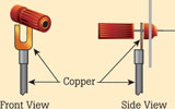
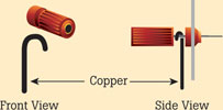
In low resistance measurements, the first requirement is for cable/connector resistance to be low and constant. Using spade lug connectors under securely tightened binding posts (Figure 2) or simply a bare solid copper wire (Figure 3) is recommended.


Precision measurements in low resistance applications, such as two-terminal resistors, generally begin below 10 kΩ. However, for measurements in the 100 ppm uncertainty range, considerations of low resistance techniques may be reduced to 1 kΩ or less. Using four-terminal techniques minimises the effects of cable and connector lead and contact resistance. Most modern calibrators and laboratory DMMs have built-in features that nullify the effects of lead resistance by using remote sensing techniques.
High resistance applications
A very high proportion of the calibration laboratory work load may include calibrating DMMs and measuring high resistances. This is where high quality banana plug cables really shine. Not only does connecting spade lugs to equipment take valuable time, but many meters with millivolt ranges (where thermal EMFs are a problem) do not have binding posts which even allow use of spade lugs.
Also, in high resistance applications a cable must have very high insulation resistance. Commonly, either polytetrafloroethylene (PTFE) or Teflon is used as the insulation material. Either of these will have the normally required ≥1012 Ω or greater insulation resistance.
Insulators commonly used for low voltage wiring may not have high enough insulation. Should this kind of wire come close to a low point in the high resistance circuit, it will cause the high impedance to be shunted, possibly causing an undetected error. Wire with a shiny plastic coating will usually have the required insulation qualities. Low voltage wire coated with other materials should never be used for high resistance applications.
AC applications
In general, all the factors applying to the various DC and resistance applications also apply to AC. However, there are a few additional conditions to be considered.
Cable capacitance
The major differing factor to consider for AC is the effect of cable capacitance on the measurement. The AC source, in addition to supplying the current required by the load, must also supply the current to drive the capacitance represented by the cable attached to its output terminals. Therefore, it is always advantageous to keep the cable capacitance as low as possible.
A cable with the lowest possible capacitance is a pair of unshielded wires separated by several centimetres. This will work at relatively high voltage values in relatively low impedance circuits. An example would be calibrating a source at levels of 0,5 V or higher and at frequencies up to 500 kHz.
However, sourcing voltages at the millivolt level into the higher input impedance of electronic voltmeters or DMMs may lead to problems with excessive noise pickup due to lack of shielding. Also, at frequencies of 1 MHz and above, the cable inductance begins to reduce the signal delivered at the end of the cable.
These two problems are best solved by using a high quality, shielded, insulated, twisted pair cable. Such a cable should have a capacitance rating below 66 pF per metre. Also, a twisted pair minimises the cable inductance as well and will work quite well up to around 1 MHz. It also effectively prevents EMFs from affecting the measurement.
Using coaxial cable
One of the greatest surprises to the uninitiated is how quickly the capacitance of coaxial cable can run up with just a couple of metres. For example, one of the most common types (RG 58U, a 50 Ω RF impedance cable) runs around 98 pF per metre. If the source impedance is significant, a reduced signal will occur at the end of the measuring cable. Therefore, for the greatest precision AC work, shielded twisted pair cable is recommended. Coax should only be used in moderate accuracy situations.
Cable maintenance
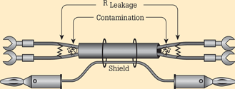
Time and usage will cause gradual deterioration of any cable and connector. Visual inspection can detect the obvious problems of corroded cable connectors, or even frayed cable strands where the connector is mated to the conductor. Before using unknown quality cabling for the first time, an ohmmeter should be used to check the cable while flexing it for any detectable variation. Cable strands can become broken internally (Figure 4). When this happens, the strands can make intermittent contact as the cable is flexed.

Cable maintenance for the spade lug type may include re-termination of the lugs when broken strands are evident or simply cleaning the lug if it is oxidised. Usually, the broken strands will be near the end of the cable where most of the flexing occurs. That means the cable can probably be clipped back a couple of centimetres, stripped and soldered to a new lug. The soldered area should then be covered with heat shrinkable tubing to protect against surface grime and lend some rigidity to the connection.
Cleaning oxidised spade lugs is quite easy, using a pencil eraser that is not contaminated with pencil lead. Although surface contamination on the outer insulator of a cable is normally not a serious problem, except in terms of aesthetics, it could be of considerable concern in high voltage measurements. The area of concern is at the cable ends where surface contamination can connect the area between both conductors. This could create a leakage path when measuring in high impedance circuits. Cleaning this area with denatured alcohol can remedy the situation.

Summary
In summary, there are many factors that affect measurements that are not necessarily pointed out in calibration procedures. The information contained in this article is meant to help minimise uncertainty due to choosing the wrong cable for the setup, inappropriate connections, or problems caused by inadequate preventative maintenance.
For more information contact Comtest, +27 (0)11 608 8520, [email protected], www.comtest.co.za
| Tel: | +27 10 595 1821 |
| Email: | [email protected] |
| www: | www.comtest.co.za |
| Articles: | More information and articles about Comtest |

© Technews Publishing (Pty) Ltd | All Rights Reserved