Printing using micro stencils for LGA/QFN rework
20 February 2008
Manufacturing / Production Technology, Hardware & Services
Bob Willis, process engineering consultant
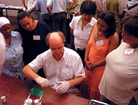
Bob Willis shows off his new gloves to SMART Group workshop delegates
If you are repairing land grid array (LGA) or area array devices, should you print the circuit board or the device terminations? What is easier and more repeatable? It depends on your own skills. Which one works? They both do.
Hands on rework workshops for SMART Group South Africa held late in 2007 proved very successful for the author and delegates reworking these fairly new packages. Special thanks go to Tecan in the UK for making the handheld manual rework foils specifically designed for QFN (quad flat no lead) and LGA packages.
What follows is a step-by-step guide to the process.
Make sure that the solder paste being used in rework is the same as in production. Often a dispense grade with larger ball size or lower metal content is used in repair areas but may not be suitable for stencil printing these fine pitch parts.
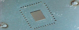
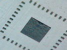
Select a micro stencil for the component footprint for a land grid array; this would normally be 100 μµm foil. The stencil apertures for the outer pads are produced as one to one apertures. The centre aperture can be a single or multiple apertures to cover between 50% and 60% of the surface area. It is recommended to have the paste printed to the centre of the device and not to the edge of the centre pad.
Hand print stencil for LGA package with 100 μm foil
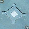
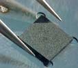
The stencil, being very thin, has a backing foil of between 250 and 300 μm thick, which allows the stencil to be used for manual hand printing. The thicker support foil prevents the image foil from being flexed during printing, which can lead to inconsistent deposits. The support foil also allows the component to be positioned accurately to the terminations.
Laminated support foil welded to stencil foil, providing a location for the package alignment
Place the LGA/QFN component into the stencil guide and check that the right stencil is being used and that the apertures are perfectly aligned with the terminations. One finger can be used to hold the component in position while the stencil is turned over for printing. Alternatively, a small piece of Kapton tape can be used to hold the part in position.
LGA is located in the support foil cavity for printing
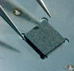
The component can now be printed with solder paste using a small metal rework squeegee blade. It is important to use the blade in the same way as a printer; make sure the paste is rolling and the surface of the stencil is clean after the print stroke. Confirm that the paste is completely filling the apertures.
Stencil is turned over while still holding the LGA in place and manually printing with solder paste
Before printing solder paste onto components, try printing paste images onto a flat surface like copper clad laminate, glass or thick white card. This will allow an opportunity to perfect the repair printing process. When the correct technique has been mastered, check the cleanliness of the stencil apertures and base to prevent contaminating the component surface with paste.
The LGA is lifted from the cavity and placed on the printed board for reflow. Alternatively the stencil is located on a rework system so the machine can lift the printed component directly and place the part on the surface of the board
Turn the stencil over so that the part can be lifted prior to placement. If the component is lifted manually it can be inspected visually prior to placement on the board. If the stencil is going to be located on a rework system, the component can be placed automatically, and inspection of the paste deposits can be conducted on the rework system when the component is aligned with the pads prior to placement.
LGA with solder paste after the printing process
For more information visit www.askbobwillis.com
Further reading:
The ultimate range for design and repair
RS South Africa
Manufacturing / Production Technology, Hardware & Services
Whether adapting existing systems or maintaining essential equipment, design and repair play a crucial role in ensuring efficiency and longevity.
Read more...
Next-generation SPI and AOI series
Techmet
Manufacturing / Production Technology, Hardware & Services
Saki Corporation has launched its next-gen series for SPI and AOI featuring a modular design for enhanced inspection efficiency and automation.
Read more...
Yamaha’s Advanced Safety Package eases factory-safety
Truth Electronic Manufacturing
Manufacturing / Production Technology, Hardware & Services
Yamaha Robotics SMT Section has extended availability of the Advanced Safety Package, which contains optional features to elevate printer and mounter safety above and beyond mandatory levels.
Read more...
Case Study: Siemens Valor automation solution
ASIC Design Services
Editor's Choice Manufacturing / Production Technology, Hardware & Services
Electronics manufacturer BMK used Siemens Valor to enhance accuracy and speed up bill-of-materials quotations.
Read more...
The factory beat
Electronic Industry Supplies
Manufacturing / Production Technology, Hardware & Services
Change is the only constant across today’s complex manufacturing landscape. The surge of digital transformation, spearheaded by Industry 4.0, has redefined how factories operate, build, and evolve.
Read more...
Microtronix powers up 2025 with smart meter production for Eskom
Microtronix Manufacturing
Manufacturing / Production Technology, Hardware & Services
Microtronix has kicked off 2025 with a significant milestone: the production of smart meters for Eskom, designed to assist customers with load reduction initiatives.
Read more...
Reliable X-ray inspection system
MyKay Tronics
Manufacturing / Production Technology, Hardware & Services
Inspecting long PCBs that are often used in sectors like telecommunications, automotive, and energy, where high reliability is required, presents several unique challenges.
Read more...
G-Tera high-speed SMT printer
Techmet
Manufacturing / Production Technology, Hardware & Services
The new generation of automatic printing presses from GKG, the all-new G-Tera, is equipped with a 3,0-megapixel LIGHT-Bolt CCD camera, an upgraded conveyor system, and an enhanced printing system.
Read more...
Extending AI assistance in AOI
Yamaha Motor Europe N.V.
Manufacturing / Production Technology, Hardware & Services
Artificial Intelligence is renowned for image recognition and classification skills, suggesting a great fit with the objectives of automatic optical inspection.
Read more...
Design & Repair range from RS Pro
RS South Africa
Manufacturing / Production Technology, Hardware & Services
The launch of the new RS PRO Design & Repair range caters to a wide array of industries, including discrete and process manufacturing, energy & utilities, facilities management, and intralogistics.
Read more...


 printer friendly version