
Ref: z2920153m
MicroTCA opens up new possibilities for the use of AMC assemblies by directly plugging the modules onto the backplane. The resulting systems are extremely compact and efficient and are outstanding as solutions in the areas of telecommunications, medical technology and complex automation systems.
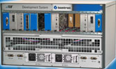
MicroTCA Release 1.0 was published in July 2006 as the standard of the PICMG (PCI Industrial Computer Manufacturers Group) for system architectures with AdvancedMC modules. The standard uses the AdvancedMCs already developed and available for AdvancedTCA without any changes, directly in its own small chassis. This increases considerably the possibilities for using AMC modules. Among the new possibilities are, for example, compact carrier-grade systems and, in general, systems with high system performance and availability requirements. Systems for use in communications, data processing and control can therefore be designed, with the help of commercially available standard components.
As with AdvancedTCA, MicroTCA also supports hot-swap and an autonomous system management. Likewise, MicroTCA has at its disposal, a switched fabric, supports redundant configurations and makes possible extremely high data throughput via diverse transport systems (among them GbE, PCI-Express, Fibre Channel and Serial Rapid IO). The first systems for evaluation and development of MicroTCA-based solutions are available.
This article gives an overview of MicroTCA configurations.
The MicroTCA kit
The core components of every MicroTCA system are the AdvancedMC Modules. The prevailing platforms have a robust and small form factor: the dimensions of single-width assemblies are 73,5 x 183,5 mm, double-width assemblies are twice as wide. Both systems are available in Compact Size with half the height (half height with three units), Mid Size with four units and Full Size with full height (full height with six units). All the modules described in this article are Full Size in single-width design. The AMC modules are identical to the modules specified and available for ATCA. In contrast to ATCA however, with MicroTCA the AMC modules are plugged directly onto the backplane. Functions specific to MicroTCA are thereby distributed among the following components: (1) the AMC modules, (2) the backplane and (3) the MicroTCA Carrier Hubs, or MCH. Figure 2 gives an overview.
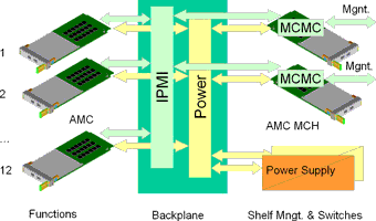
The AMC modules are fixed components of every MicroTCA system. The system shown in the illustration can incorporate 12 commercially available modules, for example. For this, the backplane takes over power distribution via redundant power modules and the distribution of signals for shelf management via the IPMI interfaces (Intelligent Platform Management Interface). The AMC carrier IPMI controller is situated in the MicroTCA Carrier Hub. Since MicroTCA builds on conventional AMC modules, this Carrier Hub plays a very special role. The IPMI management controller can be found there under the designation MicroTCA Carrier Management Controller (MCMC). MicroTCA systems can be populated with one MCH or redundantly with two MCH modules, as shown in the illustration. On the front side of the MCH modules, there are interfaces designated 'Management' for administrative functions (alarms, errors, configuration management) and for support in the evaluation phase (debugging).
A special component, the MicroTCA Carrier Hub (MCH)
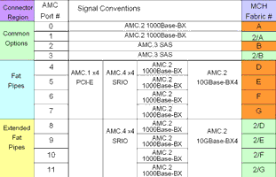
The most important function of the MCH is the provision of all signals necessary for the AMC modules. The functions that are, in principle, necessary for every system are provided by the MCH as common options. Among these are the IPMI functions already mentioned, Clocks, JTAG, the individual radial networking of the modules with the MCH via GbE ports and the provision of interfaces for disks via SATA or SAS. The common options are offered as fabric A and B from the point of view of the MCH and the backplane. Additional options for networking can be offered as Fat Pipes and Extended Fat Pipes with the designation fabric D, E, F and G.
Main feed-in with common options
The distribution of signals to the AMC modules is via the backplane. At this point there is room for various design options. MCH modules can be configured in various expansion stages with one to four connectors (tongues) for the backplane. For the distribution of the signals offered in each case, there are, in turn, some options within the backplane. The standards by which all things are measured are the available AMC modules and the usual conventions for them, especially for the common options, and the system’s intended area of use. Figure 3 shows the simplified representation of a backplane configuration.

For the signals offered, the MCH modules have exposed slots in the system that are situated on the edges of the system in the illustration (the pluggable power modules farther on the edge are not shown in the illustration). The system shown in the illustration has slots for up to 12 regular AMC modules. Among the conventions are radial and redundant networking of AMC ports 0 and 1 to the MCH slots, with GbE as one of the common options. In this way, a redundantly-designed MicroTCA system with two MCH modules makes possible a dual-star configuration of all modules. For this, the first MCH provides a GbE switch with a port for port 0 of each AMC module (fabric A). With a redundant configuration, the second MCH module provides in each case an additional GbE port for port 1 of each AMC module. The AMC ports 2 and 3 with SATA or SAS for the connection of disks can likewise be distributed radially (fabric B of the MCH), or configured according to the individual system. For the distribution of the common options including IPMI, clocks and JTAG, an MCH requires two connectors (tongues) on the backplane.
Individual configuration possibilities with fat pipes
Ports 4, 5, 6 and 7 of the AMC modules can be used with various transport systems, eg, with PCI Express, GbE, Serial Rapid IO or 10GbE. For each port of an AMC module, the MCH provides the required signals. The distribution is in turn the task of the backplane. Multiple configuration possibilities now arise here. For example, radial networking of all AMC modules to one of the MCH, or radial networking of a selected portion of the modules (ie, selected slots) to one of the two MCH, or to both MCH, as represented in Figure 3. In addition, there is the possibility of configuring the AMC ports 4 through 7 point-to-point between selected slots. Figure 3 shows a combination of these possibilities. Among the additional possibilities is operation of the system with several protocols or transport systems.
The backplane network of a MicroTCA system results from the configuration of the backplane and the MCH module. In the example shown in Figure 4, the MCH modules are dual-star networked with all slots via GbE ports. This networking is carried out on the MCH in each case with 2 uplinks with 10 GbE interfaces. The system thus has a very high data throughput to each of the connected AMC modules at its disposal, which is especially interesting for systems for control (controllers) and for systems with high data throughput. For this networking, the main feed-in with the help of common options is enough. The capacity for the transport of data can be further increased and with the help of fat pipes can be individually configured. In extreme cases, radial networks are possible from the MCH to each individual AMC module, which does not really yield a useful configuration for a compact system with a high functional range.
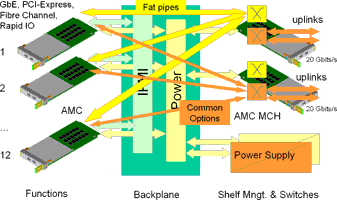
Figure 5 from the MicroTCA specification shows the MCH connections on AMC ports through the backplane. Among the configuration possibilities described so far are the common options and fat pipes. Figure 5 shows the appropriate ports of the AMC modules and possible configurations with one or two MCH. Additional configuration possibilities (eg, dual-star networks of the user plane with redundant MCH) result from use of 'extended fat pipes'.
Sample configurations and development systems for evaluation of usefulness
In practice, a given configuration depends first on the available AMC modules and on the individual system requirements. While ATCA systems are used mainly for highly available, high performance systems in the core networks of telecommunications (call server, media gateways, media server, trunking gateways, IMS), MicroTCA systems are suitable for compact solutions in the area of access networks (base stations, base station controller, access controller, DSL line termination, network access systems). In both families of systems, AMC modules are used as components. To conclude this brief overview of MicroTCA, Figure 6 shows a redundantly-configured MicroTCA system that makes use of some of the configuration possibilities described.
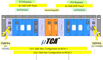
Both MCHs offer system access with high data throughput with the help of the two 10GbE interfaces designated as 'uplinks'. In addition, the MCHs on the front side have fast Ethernet interfaces available for debugging and management. The common ports 0 and 1 of the connected AMC modules can be reached radially from each of the two MCHs. Ports 2 and 3 are configured for connection of SATA or SAS memory modules to selected slots. Ports 4 through 7 are configured individually in the sample shown: Between slots 1 and 4 (and 9 and 12), PCI Express systems can be used for communication between the CPU module and the appropriate I/O module.
The DSP modules on slots 6 and 7 can each be provided with data by one of the MCHs via GbE systems. For communication between the DSP modules, a Serial Rapid IO system can be used in addition. Illustration 5 is an example that is supposed to show the fundamental configuration possibilities. In practice, the optimal configuration in each case results from the individual requirements and the selected AMC modules. Here, practical experience must inform the decision of the appropriate solutions for the intended purpose. The I/O components shown in the sample configuration make it possible the networking of the system via IP-based protocols. For practical use in access networks, depending on each application, additional special interface modules are necessary, such as E1/T1 for ISDN or signaling CS7, or STM-1/OC3 or STM-4/OC12 with ATM or POS.
The high data throughput and achievable redundancy with MicroTCA systems, which is not possible with separately configured systems, is of particular interest for highly available applications. MicroTCA makes redundancy possible within the shelf or chassis at the level of the AMC modules and the backplane. The switches directly integrated into the system or into the MCH provide for high data throughput and, at the same time, an effective configuration during operation in connection with IPMI. Interface assemblies can be brought directly into this network.
For more information contact Peter Ahne, Kontron Modular Computers, +49 (8341) 803-0, [email protected]
© Technews Publishing (Pty) Ltd | All Rights Reserved