


In addition to having a high melting point, lead-free solders are very aggressive towards metallic materials. Adapting the soldering parameters to the new process conditions required for lead-free soldering often results in degradation of the tools that come directly into contact with the solder.
In addition to technical problems, economic aspects are a key factor. This article from Cooper Tools describes a test in which the destruction of soldering tips during lead-free soldering was examined.
For the switch from lead-based solders to lead-free solders, the tin-silver-copper-based solders, or tin-copper-based solders, are favoured. Due to the high melting points involved, all soldering parameters for soldering processes have to be re-determined and reconfigured. Soldering temperatures are a significant aspect. Theoretically, for wetting reasons, the temperature must be increased by approx. 40°C in order to achieve the same process times. However, this is normally not feasible, because the materials to be soldered are generally unable to withstand such high temperatures. Soldering machines and tools also present major problems, which can be alleviated by optimising the process. Specifically in the case of copper bit soldering, the useful life of the tips is reduced significantly by the longer soldering times and higher peak temperatures involved. Anyone who does a lot of soldering with a soldering iron, and has switched to lead-free soldering, will have had this unfortunate experience.
New micro-alloyed soft solders
In a study, the effects of alloy temperature and flux on the useful life of soldering tips was investigated. Regular lead-free alloys were compared with equivalent, microalloyed solder alloys of the type Flowtin with improved properties. The comparison between SnCu or SnAg3.8Cu0.7 and Flowtin TC or Flowtin TSC shows that the wetting forces of all alloys are identical, which means that the micro alloy has no affect on the practical aspects of copper-bit soldering (The designations TC and TSC are specific abbreviations for lead-free alloys and equivalent SC and SAC alloys). There are significant differences in the dissolution rates. This is particularly the case with the copper dissolution rates of the micro alloy.
The results of the dissolution tests on Cu specimens are shown in the diagram (see Figure 1). In the case of all Flowtin alloys incorporating the solutions obtained by extensive testing for optimised micro-alloying additives, the dissolution rate is greatly reduced. As usual, the dissolution rate is temperature-dependent and increases exponentially with rising temperature.
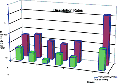
In the case of micro-alloyed solders, however, the relationship between the dissolution rates (dissolution deceleration) remains the same. In our view it is necessary to qualify the statement 'however, at a lower level'. It is, therefore, possible to solder thin layers or thinner copper wires using lead-free alloys.
Dissolution of iron
The dissolution rate of iron (steel ST37) in a static solder bath was determined at a temperature of 350°C at 0,37 mm per hour.
Flowtin TC - micro-alloyed Sn99.3Cu0.7 - was used as the test alloy. Theoretically, an iron layer 200 mm in thickness will be dissolved in about 400-500 hours, approximately twice as long as with the non-microalloyed, lead-free SnCu0.7 solder.
Degradation of soldering tips
Each soldering tip degrades when in use. There are a variety of reasons for this:
1. Contact with liquid solder - metallic reaction, dissolution.
2. Contact with flux - chemical reaction, corrosion.
3. Abrasion due to cleaning and abrasion caused by soldering surfaces - mechanical damage.
The metallic reaction and the dissolution rate are dependent on: the solder used, the soldering tip surface and, to a high degree, the temperature.
Depending on the solder alloy, the dissolution rates increase by a factor of 2-4 after the switch to lead-free soldering. Since lead has a slow reaction rate and hardly reacts with iron and copper, the high tin content in lead-free solder alloys is the key factor responsible for the increase in the dissolution rate. Like in all chemical processes, the reaction rate increases exponentially with rising temperature. Therefore, the metallic and chemical destruction of soldering tips is also a question of temperature.
The soldering tips have to be cleaned, because only a freshly tin-plated soldering tip will be readily wettable and therefore suitable for use in the soldering process. Mechanical damage occasionally occurs in practice, but will not necessarily result in destruction of the soldering tip. It is often the case that maltreated soldering tips are not detected straight away, if at all. There is much literature available on the correct handling of soldering tips and therefore will not be further discussed here.
Tests
Tests were conducted in order to examine the effects on soldering tips of lead-free alloys (as well as micro-alloyed variants thereof), temperature and flux.
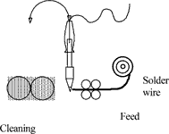
Test set-up: soldering iron; Cooper Tools' Weller LR82, 80 W, HT2 tip with 60 mm iron coating. Soldering robot running the following program: tin feed 2,4 s; dwell time 1 s; cleaning time 0,2 s; soldering tip check - inspection after 50 cycles.
The number of soldering cycles until break-through was observed. To reduce cycle times, only a 60 mm iron coating was applied to the copper core.
Results
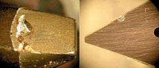
The following figures show a typical defect, obtained using the TC Kristall 400 solder wire. After 1250 cycles, surface pitting has formed on the wetting side. Surface pitting has, however, not formed on the contact side. Because the tin is distributed over the entire wettable surface, surface pitting can occur elsewhere.
General defect patterns
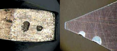
In almost all tests, surface pitting occurred in the contact zone of the chromium plating. As shown, the chromium plating is also slightly pitted. The micrograph shows that the tin has begun its destructive work and rapidly cavitates the copper core (Figure 3).
There are several situations in which break-through of the tin can occur: on the wetting side where the wire is melted off, break-through occurs beneath the chromium plating. Break-through can also occur on the back, because the liquid solder envelops the entire wettable surface, see Figure 4.
The micrographs illustrate that the dissolution rate of the iron coating is relatively constant. As in all cases, the dissolution rate is heavily dependent on temperature.
Effect of temperature
The destruction of soldering tips is heavily dependent on temperature. The higher the peak temperature, the quicker break-through occurs at the soldering tips.
Graph 1 shows the degradation of the soldering tip as a function of temperature. The same alloy, but two different fluxes are used. The front row shows the degradation that occurs in the case of Kristall 400.
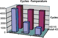
The rear row represents the degradation with flux KS115. The effect of the flux can clearly be observed. The halogen-free flux is evidently much more active at high temperatures and destroys the soldering tip relatively quickly. The halogen-based activators in the KS115 flux evidently degrade relatively quickly, and therefore have a much less aggressive effect on the soldering tips.
Effect of solder alloy
The solder alloy used is a significant factor influencing the rate of degradation. As Graph 2 illustrates, the micro-alloy increases the number of soldering cycles significantly in all three cases, and in most cases is more than doubles the number of soldering cycles. The wire flux used is Kristall 400, the soldering iron temperature was 385°C.
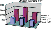
The dissolution behaviour of flux KS115 is slightly different. The number of soldering cycles is generally much higher than with Kristall 400. In this case, too, a significant improvement can be observed by using the micro-alloyed variant. Only in the case of alloy type TSC263 was this behaviour not observed (Graph 3). There is no obvious reason why this combination should behave differently, and further tests will be performed to clarify whether this is attributable to another effect not considered until now.

The effect of the micro-alloy additives can be clearly observed. There are major advantages for copper bit soldering and machine soldering. In addition to the alloy, the flux used has an effect on the dissolution, and hence the useful life of soldering tips. Fluxes with a high resin content provide the best protection. Both effects can be combined, thus keeping wear to a minimum.

Summary
New SnAg, SnCu and SnAgCu based lead-free alloys of the type FLOWTIN were tested as solder wire. The results show that micro alloyed solders of the type FLOWTIN are advantageous. Cobalt is suited best as the primary component of the micro-alloy. It has been found that a combination of other ferrous metals delivers better results. In this way, the total doping concentration is kept as low as possible (<500 ppm). The low doping concentration does not alter the physical properties of the primary alloy.
The reduced dissolution rates are advantageous in several respects. They allow the soldering of thin circuit board conductors and wires. Multiple solders are easier to perform, particularly in the case of high-temperature soldering. The described micro-alloyed solders involve a minimum of material fatigue and are less aggressive towards equipment and materials. These are advantages which cannot be achieved using regular lead-free solders. Through the combination of micro-alloyed Flowtin solder and fluxes such as KS115 or KS110, the useful life of soldering tips can be extended considerably. In cases where good heat transfer is required and a thick iron layer over the copper core on the soldering tip would be an obstruction, standard iron-plated soldering tips can be used. This can help to cut costs slightly.
The tests to determine the degradation of soldering tips were conducted at Cooper Tools, Besigheim. Flowtin solder wires were manufactured and made available for testing by Stannol.
| Tel: | +27 11 704 3020 |
| Email: | [email protected] |
| www: | www.testerion.co.za |
| Articles: | More information and articles about Testerion |


© Technews Publishing (Pty) Ltd | All Rights Reserved
 printer friendly version