


Understanding signal propagation effects can help when estimating the performance of transmitters and receivers designed for remote-keyless-entry (RKE) applications.
Remote-keyless-entry (RKE) systems unlock cars from a distance by transmitting a coded radio signal over the air from a key fob to a receiver in the car. The receiver decodes the signal and controls an actuator that opens the door. An important performance benchmark of an RKE system is its useful range. This range is determined by a link-budget calculation. The most crucial factors of this calculation are the power transmitted from the key fob, receiver sensitivity, and path loss. Transmitted power can be improved by carefully matching the transmitter to the small antenna in the key fob. Sensitivity can be improved by using phase-locked-loop (PLL) transmitters, such as the Maxim MAX1479, in conjunction with PLL RF integrated circuit (RF IC) receivers like the MAX1471.
Path loss depends on the distance between the transmitter and the receiver, the radio transmission's frequency, and the height of the transmitter relative to the receiver. In an 'empty parking lot' environment, the most significant characteristic of path loss over more than a few metres is that it varies as the fourth power of the distance instead of the square of the distance in free-space transmission. Path loss is, in fact, independent of frequency. It obeys a very simple equation for small antennas with unity antenna gain:
Lp = h2²h1²I2R4 ………… (1)
where R is the horizontal distance between transmitter and receiver, h1 is the transmitter height, and h2 is the receiver height.
'Ground bounce' is responsible for this compact, easy-to-remember equation for path loss. In any location near the ground, the radio transmission takes both a direct path and a ground-bounce path from the transmitter to the receiver (Figure 1). The ground-bounce contribution can be thought of as a reflection from a mirror. It is reflected with a 180° phase shift for conventional terrain. In addition, it travels a longer distance than the direct contribution. The two contributions recombine at the receiver, where they would cancel completely if not for the path-length difference.
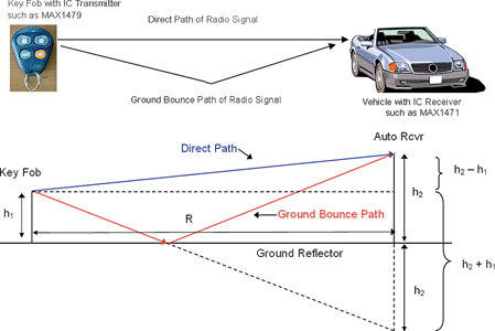
The direct and ground-bounce distances are given by Equations 2 and 3:

For R, R1, R2 >> h1, h2, these expressions are approximated by Equations 4 and 5:
R1 ≈ [R1 + ½ h2² + h1² - 2h2h1)]IR² ………… (4)
R2 ≈ [R1 + ½ h2² + h1² + 2h2h1)]IR² ………… (5)
The difference between the two distances is given by Equation 6:
ΔR = R2-R1 ≈ ½ R(4h2h1IR²) ≈ 2h2h1IR ………… (6)
Ground-bounce is a simple example of multipath transmission. A transmitted radio wave reflects from multiple surfaces. As a result, multiple signals with different amplitudes and delays arrive at the receiver.
In free space, under line-of-sight conditions, there is only one transmission path. The signal power at the receiver is given by Equation 7 as:
PR = PTGTGRλ²/(4πR)² ………… (7)
where: PR = the received power; PT = the transmitted power; GT = the transmitter antenna gain; GR = the receive antenna gain; and λ = the wavelength.
Recall that when the ground is present, the transmitted power takes two paths: direct and ground-bounce. There are many ways to model this transmission. Most of them are worthy of a graduate thesis. A reasonable and intuitive way to show the effect of the second path is to assume that half of the power goes into the direct path while the other half goes into the ground-bounce path. Consequently, two voltages with slightly different phases subtract at the receive antenna. (Remember the 180° phase reversal of the reflection). Equation 8 shows the complex number representation for the combination of these two voltages:
VR = V1 - V2e-jπΔR/λ = V(1 - e-jπΔR/λ) ………… (8)
The two voltages, V1 and V2, are virtually the same in magnitude for most flat-ground conditions. We can consider V to be a 'voltage' (in this case, V/Ω½) that is equal to the square root of half the received power or as in Equation 9:
V = (PR/2)½ = (PTGTGR/2)½ (λ/4πR) ………… (9)
The power received is just the squared magnitude of the combined voltage in Equation 8:
PR(Ground-bounce) = V²|1 - e-j2πΔR/λ|² ………… (10)
If V from Equation 9 is substituted into this and the complex exponential terms are combined into trigonometric functions, the equation for exact path loss is reduced to:
(PTGTGR/2)(λ/4πR)²[2-2cos(2πΔR/λ)] = 2PTGTGR(λ/4πR)²sin²(πΔR/λ) ……… (11)
If the approximation for ΔR from Equation 6 is substituted into Equation 11, and approximate sinx is approximate to x, the following simplified expression results:
PR = 2PTGTGR(λ/4πR)²(2πh2h1/λR)² ≈ PTGTGR(h2²h1²/2R4) ………… (12)
For small antennas with wide angular-coverage, the antenna gain is nearly-unity. Expressing Equation 12 as a ratio of PR/PT and setting GT = GR = 1 leads to the approximation that is Equation 1.
Figures 2 and 3 show plots of these path-loss equations at 315 and 434 MHz for antennas with unity gain. Included are the free-space path loss of Equation 7, the exact path loss given by Equation 11, and the approximate path loss given by Equation 12. Clearly, the exact path loss varies dramatically at close distances. It also depends on the signal frequency.
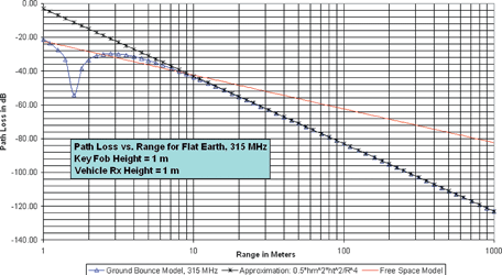

It is interesting to note from these two plots that, given the typical RKE geometry shown in Figure 1, the path loss at a 10 metre distance can be approximated by the freespace path loss. The direct contribution and ground-bounce contribution are separated in distance by about one-quarter wavelength at 300 to 400 MHz. The result is a 90° phase difference, which means that the two contributions add neither constructively nor destructively.
At distances greater than 10 m, however, the path loss varies as R-4. The expression in Equation 1 is thus a very useful quick calculation for path loss at moderate to long distances from the vehicle. For equal transmission and reception height, h, the path loss in dB is simply:
Path loss (dB) = -40log10(h1 R)-3 ………… (13)
For a transmitter and receiver at 1 metre heights, it follows that the path loss at 1 km is -123 dB.
Tips for using path-loss calcs
The manner in which the power from the transmitter is split between the direct path and the ground path is not exact. As a result, the expressions in Equations 12 and 13 sometimes have a factor-of-2 variation (depending on the model). Note that the expressions in this article closely approximate the best range performance achievable. They also describe how path loss varies with height and distance.
The free-space loss model can be used for ranges under 10 m from the vehicle. One must keep in mind, however, the fact that wide variations can occur from the ground-bounce reflection within that 10 m. For ranges greater than 10 m in obstruction-free environments, the R-4 approximation can be used.
The presence of any other scattering surfaces increases the variation in path loss at any given distance. Any obstacles (other cars in the parking lot, light poles, low buildings, etc) create more bounce paths. They diffract the radio waves and - in the case of concrete buildings - attenuate them. The R-4 loss behaviour is therefore optimistic even though it seems bad compared to free-space loss.
In a realistic setting, a good guideline is to subtract 20 dB from the 'empty parking lot' loss in Equation 1. This will allow for the instantaneous fading that comes from multiple surfaces. If the key fob is inside a building (for instance, in a remote-start application), subtract 30 to 40 dB from the loss. In the final analysis, the most reliable way to determine maximum range is through empirical testing. The approximations above are a reference point or 'sanity check' from which to start the measurements.
| Tel: | +27 11 608 0070 |
| Email: | [email protected] |
| www: | www.cstelectronics.co.za |
| Articles: | More information and articles about CST Electronics |
| Tel: | +27 11 458 9000 |
| Email: | [email protected] |
| www: | www.electrocomp.co.za |
| Articles: | More information and articles about Electrocomp |


© Technews Publishing (Pty) Ltd | All Rights Reserved
 printer friendly version