Forced-air convection, being the preferred technology for solder reflowing surface mount assemblies, represents a shift from infrared (IR) and other methods for reasons solidly based on principles of physics and highlighted by the accelerated push to lead-free soldering. For example, the varying emissivities of components populating a printed circuit board (PCB) assembly make IR-heater technology undesirable in many cases.
Also, because IR emits its effect via radiation, its straight-line energy transfer creates shadowing, a condition in which smaller and lower profiled components in proximity to larger and taller parts are exposed to nonuniform radiation. However, for its part, some significant difficulties remain with current forced-air convection technology that call for correction.
Differentials: from temperature to directional
* Temperature differentials. One of the more significant improvements offered by forced-air convection over IR technology is convection's propensity to reduce temperature differentials across the PCB. Even with convection, however, the centre of the oven remains hotter than the outsides because oven chambers naturally cool from the outside in. This condition compels the process engineer to create profiles that are hot enough to reflow components on the periphery of the board, thus risking overheating and damaging sensitive components near the centre.
Similarly, convection ovens generally impinge hot air to the topside of board surfaces with one set of heaters and to the bottom side using a second set of heaters. Any temperature disparity between the sides induces stress in PCB material, and can contribute to defects such as board warping and delamination.
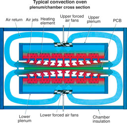
* Air-volume differentials. In the typical forced-air convection oven, the hot-air stream impinged on the assembly continues to travel toward the oven's periphery. Now cooler, the air is recaptured through a plenum, reheated and redirected at the PCB (Figure 1). Thus, the volume of air impinged on any point in the centre of the board is significantly lower than that to which the periphery of the board is exposed. This is because the periphery not only receives the air directly impinged on it but also the cooler air travelling past it on its way back to the plenum.

This phenomenon poses several inconsistencies:
1. The air volume to which a given point on the PCB is exposed is different than that of a point in another (longitudinal) position. Under differing air-volume flows, the volatiles escape from the solder paste at different rates, thus creating inconsistent flux activation and flux dry-out conditions.
2. The periphery of the PCB is exposed to higher air volumes but at lower temperatures, further aggravating the centre hot-spot/cool-outside condition.
3. Most convection ovens use a system of evenly-distributed ports that create streams of air commonly referred to as jets. However, the volume of air at a point directly under each jet is significantly different than that at a point between the jets.
* Velocity differentials. On one hand, increased velocity of forced air accelerates the efficiency of heat transmission to the component. On the other, an excessive velocity actually can unseat or blow off parts from their precise positions. Related to this are two detrimental factors created in most oven designs: velocity must be sufficiently reduced to prevent the unseating of components that lie directly below the jets (further diminishing the efficient transmission of heat to areas not directly targeted by a jet), and various points on the periphery of the PCB are exposed to greater velocities, ie, the air passing over the periphery is a combination of directly impinged air and air that is travelling outward from proximal locations. Velocity is increased whenever a greater volume of air travels through a fixed cross-section.
* Pressure differentials across a PCB induce inconsistencies congruent to those caused by differential velocity and differential volume. As with velocity problems, a high-pressure area is created at the centre of the impinged area of each jet. Also, a generally greater pressure is detected on the distal (farthest from the central) portions of the PCB while a lower pressure is detected proximally. Again, this is due to a greater velocity and volume of air 'squeezing' through a fixed cross-section.
* Directional differentials also are inherent in many oven designs. With two identical components, for example, one located proximally on the longitudinal centreline of the oven and the PCB, and the other located on the distal edge, the former component is impinged upon by a jet directly above it. Thus, the angle of impingement is strictly a vector having an axis perpendicular to the plane of the PCB's surface. The distal component, on the other hand, in addition to the jet above it also is exposed to vectors approaching from proximal directions. This yields a final composite vector with an angle considerably more acute than perpendicular. Result: two identical components absorb heat at differing rates because air is impinged upon their physical geometries from different directions. This problem is magnified in applications where airflow is required between the component body and the PCB surface. For example, BGA packages, located proximally on the board, are exposed to less airflow below the component bodies than those located distally.
In summary, while there is a nearly unanimous consensus that forced-air convection is a superior method for reflowing surface mount assemblies, many experts agree that issues worthy of improvement remain with the technology. These can be addressed by improving the oven's ability to produce more uniform and consistent air temperature, pressure, volume, velocity and direction across the board.
The horizontal oven
A new forced-air oven technology called horizontal convection is emerging that promises to further reduce or even eliminate some of the difficulties described. Reducing or eliminating these problems promises to provide the process engineer the means to enlarge the constantly shrinking parameter window and improve soldering quality, especially in a lead-free process.
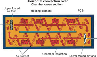
Horizontal convection is based on two principles that diverge from the conventional forced-air convection concept (Figure 2):

1. The air in each chamber is recirculated strictly within the confines of the chamber, which is designed to contain all the components needed to be self-sufficient. These components include the heating elements, fan blades, inert-gas suffusers and exhaust ports.
2. The air is circulated toward one side of the oven above the PCB and toward the opposite side of the oven below the PCB, forming a circular air current or 'cyclone' around the board via a horizontal axis longitudinal to the oven.
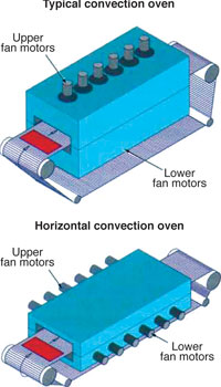
The top and bottom of the board receive the air from the outsides toward the centre, which acts to counter the centre hot-spot/cool-outside condition. Also, because both the upper and lower chambers' air continuously recirculates, temperature uniformity is ensured, minimising stress to PCB materials. Consistent and uniform volume, pressure and velocity results from passing air through equally proportioned cross-sections of the upper and lower chambers, and directional uniformity exists in the system since airflow is induced across the PCB in a direction parallel to the board's surface (Figure 3). An additional benefit of the parallel 'angle of attack' is the air stream's ability to infiltrate the spaces underneath component bodies, thus enhancing solderability of difficult devices such as BGAs and J-leaded components.

An advantageous side effect of the system is an ability to produce low oxygen ppm levels when purging with inert (ie, nitrogen) gas at reduced flow rates - available because the volume of space to be affected includes only the confines of the chamber. In current oven design, by contrast, the chamber as well as the upper and lower plenums must be purged. Lastly, because the horizontal convection system requires neither plenums nor reintroduction apparatuses, it is, due to its simplicity, more reliable and less costly.
Flux-management factor
Traditional convection ovens require a flux-management apparatus. As flux volatiles are driven from the PCB, the air or gas within the system becomes laden with their vapour, which tends to condense on any cooler surfaces. Thus, existing systems tend to collect flux condensate in cooler portions of the system such as each plenum. When permitted to condense unchecked, flux drippings within the system create severe maintenance and cleaning challenges, requiring the use of flux-management systems and expensive cooling devices to trap the flux vapours, liquefy them and drain the liquid into a collection reservoir for later disposal.
In contrast, the horizontal convection system circulates flux-laden air strictly within the confines of the heated chamber, ie, the air never contacts cooler surfaces and thus does not condense, reducing maintenance and cleaning, as well as overall system construction and operating costs.
| Tel: | +27 11 704 6677 |
| Email: | [email protected] |
| www: | www.testandrework.co.za |
| Articles: | More information and articles about Test & Rework Solutions |
© Technews Publishing (Pty) Ltd | All Rights Reserved