


Stateflow truth tables are the only construct in the Simulink and Stateflow environment that support static analysis of logical completeness. They can simplify a design that would otherwise be made from a complex flow diagram or block diagram.
Simulink and Stateflow support several diagramming constructs, such as time-based block diagrams, state machines, flow graphs, and truth tables. Each construct has its own advantages: Simulink diagrams show relationships, timing, and feedback paths quite clearly; Stateflow charts illuminate the transition sequences between logic states. Stateflow truth tables, which map actions to sets of ANDed Boolean conditions, provide a compact way to clearly specify stateless logic for complex decisions, and are especially useful for applications such as stateless mode logic.
Logic design for a turbine fuel command selector
A turbine engine runs on fuel. Putting more fuel into a running engine typically means that more speed or power is produced. Modern turbine engines employ a full authority digital engine control (FADEC) that takes in-pilot inputs and engine sensor inputs and uses them to set a fuel flow into the engine. A typical FADEC has to look at the inputs and decide what fuel flowrate to set. Many FADEC designs calculate several possible commands at each time step they run, then choose the best one for output. This decision depends on the current goals for operating the engine. The goals can be translated into operating modes, such as:
* Start the engine.
* Idle the engine without bogging down or overheating.
* Accelerate the engine without adding too much fuel.
* Hold the engine speed that was set via the pilot's throttle or the autopilot (auto-throttle).
* Ensure smooth operation and prevent damage to the engine from over-speed, over-temperature, etc.
* Decelerate the engine without extinguishing the flame inside the combustor
* Shut down the engine and let it spin (if still airborne).
Using the calculated fuel settings for different engine operation modes makes it simple to decide which setting to use. Let us assume the fuel delivery system supports a minimum flow command greater than zero. Some rules to start with:
* Hold a speed setting using a closed-loop speed governor to compute fuel flow.
* Compute minimum and maximum fuel values for current conditions and enforce at each time step.
* Calculate the maximum fuel limit as the lowest value of the protective fuel settings for over-speed, over-temperature, compressor surge, combustor overpressure, etc
* Calculate the minimum fuel limit as the highest value of the protective fuel settings for deceleration flameout and under-speed conditions, such as starting and subidle shaft loads.
One way to design this logic would be to use Min, Max, and Switch blocks in Simulink (Figure 1).
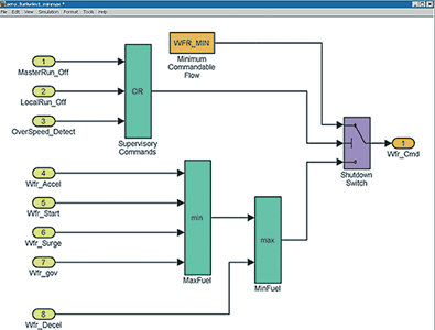
The operations are very clear in this design and, when design conditions permit, this type of approach suffices. However, the above example contains a non-obvious situation: the deceleration fuel command, Wfr_Decel, is implicitly higher in authority than the maximum-fuel values planned to protect the engine. An incorrect calculation for Wfr_Decel that unintentionally accelerates the engine is not prevented. This situation could arise from bad, yet in-range sensor data.
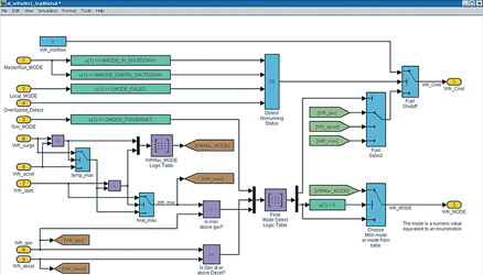
Typically, the requirements for a fuel mode selector are more complex than described above, requiring a mode variable to be set that outputs the identity of the selected fuelling mode in addition to the fuel command. The fuelling mode enables other modules in the controller software to react to the selection and make further decisions. Unfortunately, stacking Min, Max, and Switch blocks is not amenable to calculating the fuelling mode value.
Figure 2 shows the logic diagram updated to incorporate the new requirements into the design. We included logic for setting proper authority and operating mode, but this reduced the clarity of design, making analysis and logic testing more difficult.
An alternative approach is to use a truth-table-based design, which can yield higher design clarity and use automated testing for logical completeness. We made a new implementation of the fuel command selector using two simple Stateflow charts with the same inputs and outputs as the Simulink diagram in Figure 2. One chart selects Wfr_Max from three inputs and sets a temporary mode variable; the other chart contains the truth table.
Figure 3 shows the intermediate version of the truth table made during the hypothetical design process. An engineer would use the 'Run Diagnostics' button on the toolbar to check the truth table for logical completeness.
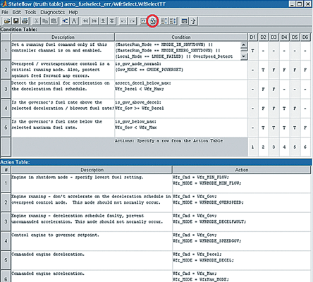
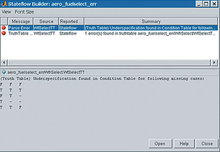
It turns out that the truth table does not handle all cases. The error dialogue box (Figure 4) shows that seven unhandled input scenarios are presented as three decision sets. Noticing that the second row is true (T) in all cases, all the missing cases appear to involve running the engine during conditions when the governor module is in a 'powerset' controlling mode (Condition 2). There is also an implicit duplication of conditions 3, 4, and 5 in the intermediate design that must be corrected. Each row of the Conditions column must be able to be true or false independently of the other rows, a requirement for a valid truth table.
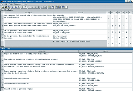
Changing the intermediate design through a combined static and run-time debugging process to handle all combinations of independent Boolean conditions ensures that the new design explicitly results in the desired behaviour. The final truth-table design does this, handling the missing cases and removing the dependencies among conditions 3, 4, and 5. Logical completeness in the table is confirmed via the Run Diagnostics button. Figure 5 shows the final design.
Stateflow truth tables complement other diagram types in Simulink and Stateflow by providing a compact format for designing complex decision logic that is easy to analyse statically, test for completeness, and debug.
| Tel: | +27 11 325 6238 |
| Email: | [email protected] |
| www: | www.optinum.co.za |
| Articles: | More information and articles about Opti-Num Solutions |


© Technews Publishing (Pty) Ltd | All Rights Reserved
 printer friendly version