


This article describes the Power-Save feature of Exar's single channel XR16L580 (L580) UART and the two channel XR16L2551 (L2551) and XR16L2751 (L2751) UARTs. Collectively, we shall refer to these three devices as the 'Low Power UART' in this article.
The Low Power UART includes a sleep mode that reduces power consumption when the device is not actively used. It stops its clock oscillator to conserve power in the sleep mode. However, the address lines, the databus and the control lines (chipselect, read and write strobes) are still active during sleep mode so that the internal registers of the device can be accessed. These signals (except the chipselect) are typically shared among many devices in the system. Any activity on these signals will translate into increased power drain from the Low Power UART thereby defeating the purpose of the sleep mode. The Low Power UART's Power-Save feature resolves this problem.
Power-save
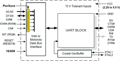
The Power-Save mode further reduces the power consumption in sleep mode by isolating the device from the databus interface. In this mode, power consumption is steady (in the range 15-50 µA at 3,3 V) and is not affected by any activity on the databus, address or control lines. However, the internal registers of the device cannot be accessed while in Power-Save mode. Figure 1 shows the block diagram of the Low Power UART. The L2551 and L2751 are very similar to the L580, the difference being the extra CS# and INT lines for the second UART channel. We now describe how the Low Power device is programmed in and out of the Sleep and Power-Save states.
Power states
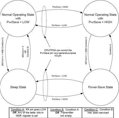
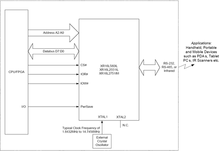
The Sleep, Power-Save as well as the Normal operating states of the Low Power UART are shown in Figure 2. The figure also shows the conditions under which the transitions between these power states take place. Since the internal registers of the device cannot be accessed while in Power-Save mode, the system design engineer must use caution if planning to use this feature. The device will emerge from the Power-Save mode only by an external event, namely activity on the RX pin or one of the other modem input pins, namely CTS#, DSR#, CD# or RI#. It is highly recommended that the PwrSave pin of the device be controlled by an I/O pin available in the system that can be controlled via software. This will provide a mechanism to access the Low Power UART in case the external event does not occur to wake up the UART. Figure 3 shows an application example when the PwrSave pin of the device is controlled via an I/O pin of the system.
Data loss during transition
When the Low Power UART has entered Sleep or Power-Save mode, the oscillator is shut off to conserve power. It takes up to tens of milliseconds to re-start the oscillator when a crystal is used to provide the UART clock. Therefore, an incoming character that is used to wake up the UART may not get assembled correctly because of this delay. On the other hand, the oscillator/buffer starts up immediately (within a few nanoseconds) when an external clock is used to provide the UART clock and is not shut off during Sleep/Power-Save mode. In applications where an incoming character on the RX pin will be used to wake up the UART, it is recommended to use an external clock and keep it running during Sleep/Power-Save mode so that the first character received will get assembled correctly. This will prevent any data loss without compromising the low power consumption during Power-Save mode.
Programming for power-save mode
The following pseudo-code snippets list the steps that are required to place the Low Power UART in sleep mode and Power-Save mode:
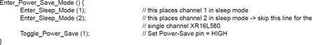
The function Enter_Sleep_mode (channel) places the 'channel' in sleep mode. In the two channel XR16L255172751 devices, this function must be called twice, once per channel.
\The function Toggle_Power_Save (state) toggles the PwrSave pin of the Low Power UART HIGH or LOW through the I/O pin of the CPU/FPGA, depending on the value of the parameter 'state'.
Finally, the function Enter_Power_Save_Mode () calls these two functions and places the Low Power UART in Power-Save mode.
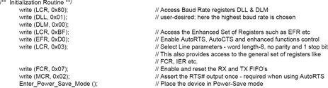
The following pseudo-code shows a typical initialisation routine and places the Low Power UART in the Power-Save mode at the end of this routine.
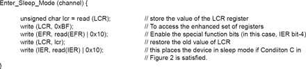
In case the event that wakes up the Low Power UART does not take place, the CPU/FPGA can claim control of the situation by getting the device out of Power-Save mode:
| Tel: | +27 11 315 8316 |
| Email: | [email protected] |
| www: | www.asic.co.za |
| Articles: | More information and articles about ASIC Design Services |


© Technews Publishing (Pty) Ltd | All Rights Reserved
 printer friendly version