


A major issue facing designers of FPGA-based systems is achieving a clean power-up. In this article we explain FPGA power requirements and the causes of their power-up problems.
We then provide a strategy for powering FPGAs and offer guidance on selecting the appropriate point-of-load DC-DC converter for each power rail.
The requirements
Most FPGA manufacturers require the core voltage (VCORE), and possibly the I/O (VIO) or other voltage rails, to ramp up monotonically to a certain voltage with ±5% steady-state tolerance, at a rate between tmin/VCORE and tmax/VCORE as shown in Figure 1.

The primary reason for the monotonic rise is either an internal power-on-reset (POR) circuit or an external supervisory reset chip that is used to enable certain sensitive analog circuitry, such as a phase-lock loop (PLL) controlled by a voltage-controlled oscillator (VCO). For example, if the voltage were to rise above the POR threshold, then dip below the trip point (outside the POR's hysteresis range) and rise again, the VCO would change frequencies and/or phase, causing the PLL to fall out of phase and lose synchronisation.
As shown in Figure 1 further complicating an FPGA power rail's monotonic ramp-up requirement is an inescapable surge current at start-up. This surge current, ICOREmax, which consists of capacitance charging current and the FPGA start-up current, can be much greater than the steady-state current, ICOREss. Each power rail of an FPGA has a minimum amount of bypass/decoupling capacitance that is used to minimise voltage troughs during load transient steps. This decoupling capacitance is usually on the order of several hundred microfarads. Using ic = C dv/dt, we can easily see that, depending on the speed at which the converter is attempting to ramp the rail voltage, the start-up current could be on the order of amperes. In addition, FPGA manufacturers specify minimum in-rush current requirements in the ampere range for some of their devices.
These in-rush currents are needed not only to charge the capacitances of the millions of internal components of the FPGA but also to momentarily supply current through a low resistance path to ground created by, for example, stacked complementary transistors that are both on. So, during start-up, the power rail's point-of-load DC-DC converter must simultaneously be able to supply a large in-rush current and to maintain a monotonically ramping output voltage with a certain dv/dt. Therefore, in addition to other components it is powering, the converter's input power supply must be capable of supplying large load currents (load transients) for short periods of time. Since these types of power supplies with low source/output impedance and fast response times are usually expensive, more often a less expensive, lower-current, slower supply is chosen; and decoupling capacitors are added to its output to lower its output impedance. Unfortunately, simply adding more capacitance to such a supply can make its response time even worse and can further complicate the ramp time and surge-current issue.
The simplest DC-DC converter: The linear regulator
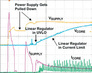
Interestingly, the simplest of DC-DC converters, the linear regulator, can cause the most problems during powering of the core or I/O voltage rails of FPGAs. Based on the set-up shown in Figures 2, 3 and 4 illustrate this point. In Figure 2, a typical bench power supply is followed by a linear regulator to power the VCCO rail of an FPGA that has a specified minimum surge current of 1,5 A (including in-rush current due to charging capacitors). Figure 3 shows the results of powering the FPGA from Figure 2 with a 3 A current-limited linear regulator and a 5 A current-limited lab supply.

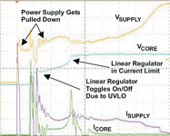
One might assume that simply using a linear regulator with a higher current limit would solve the problem. However, Figure 4 shows that this is not the case when a 9 A current-limited linear regulator, the same 5 A current-limited lab supply, and an FPGA with a specified minimum surge current of 700 mA are used.
Like most linear regulators, these regulators turn on hard at start-up and try to provide a regulated voltage within a few hundred microseconds. The regulators quickly reach their current limit and begin to operate like a constant-current source at that current limit. However, the current surge depletes the lab supply's output capacitor quicker than the supply can replenish it. The result is that the input rail falls below the linear regulator's undervoltage lockout circuit. This cycle could repeat indefinitely until the input power rail incrementally increases to a point where the linear regulator does not shut down. Surprisingly, one solution to this particular problem is to use a linear regulator with a lower current limit and possibly to increase the input power supply's decoupling capacitance. However, soft starting is the best solution.
Soft start to the rescue
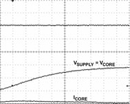
System designers seem to have fewer FPGA start-up problems when using switching regulators instead of linear regulators (assuming that the switching regulator feedback loop has been accurately stabilised). Why is this? The primary reason is that almost all switching regulators have built-in soft-start circuitry that minimises their input and therefore their output surge currents at start-up while providing a monotonic voltage ramp. Figure 5 shows the results of powering the same FPGA from Figure 2 with a bench power supply having a dv/dt of 2 V/ms.
The FPGA in-rush current is significantly reduced when the rail voltage ramps slowly. Most FPGA datasheets specify a minimum and maximum power rail ramp-up time. Therefore, using a point-of-load converter solution that includes ramp-time control is the safest way to power an FPGA.
Why use sequencing?
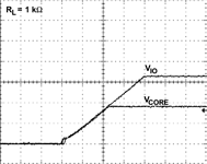
Most FPGAs do not require sequencing of their power rails; however, FPGA datasheets may specify the amount of time the rails can tolerate a specific voltage difference. Some datasheets state that powering up one rail before the other will minimise in-rush current at start-up. Regardless of an explicit requirement, sequentially ramping up power rails one after another, as shown in Figure 6, is recommended if for no other reason than to minimise the demand on the system power supply.

VCORE is usually powered up before VIO. Sequential sequencing is the easiest to implement with the output of the first rail, if the voltage is high enough, or with a supervisory circuit to control the enable pin of the second rail, and so on. Most power ICs have active-high enable signals, and many have integrated supervisory (sometimes called 'power good' or 'power OK') signals.
In some cases it may be preferable to ramp up all rails simultaneously as shown in Figure 7. Simultaneous sequencing is theoretically the most ideal form of sequencing. It ensures short-term and long-term reliability for powering the IC, since all power rails are at the same voltage during start-up; however, it typically requires external circuitry. Some power IC manufacturers are providing power ICs with integrated simultaneous start-up circuitry.
Most reliable FPGA power-up strategy
Figure 8 shows a robust FPGA power management system that addresses the previously summarised power-up requirements and start-up issues. Incorporating both soft-start and sequential sequencing, this methodology is especially useful when the system power supply capabilities either are unknown or are being taxed by other components in the system.

The supply voltage supervisor (SVS) on the input rail prevents the VCORE converter from turning on until the input rail is up and its input capacitors are fully charged. This reduces the chances of the in-rush current at start-up from pulling down the input rail and tripping the UVLO of the VCORE converter, as seen in Figure 3. The SVS on the VCORE rail may be integrated into the converter. Some type of SVS circuitry is most likely needed since the VCORE voltage is typically too low to drive the enable signal of the VIO1 supply directly. Soft starting one or more of the higher current rails further reduces the chances that start-up problems will occur.
The next design step is determining which point-of-load converter to use for each required rail. This decision depends on a number of factors, including the input supply voltage; the FPGA voltage rail and its tolerance; acceptable output voltage noise/ripple; the steady-state current; expected load transients; system size; and, of course, cost.
Which DC-DC converter?
The load current and the voltage difference between the input supply and FPGA power rail determine which DC-DC converter to use. Today's IC process node allows for FPGAs, like the Spartan-3 line from Xilinx, to operate with core voltages at 1,2 V or less. Depending on the configuration, they may require greater than 1 A of steady-state current. Meanwhile, input power supply rails have stayed at 3,3 or 5 V to power certain I/O peripherals. So, assuming that the system designer wants to use a low-cost linear regulator to derive the VCORE voltage directly from a 5 V rail, the regulator needs to dissipate (5 - 1,2)V x 1 A = 3,8 W. However, even the largest packaged linear regulator on the market cannot handle more than about 3 W without additional airflow or external heat-sinking. Therefore, step-down (buck) switching converters, whether with integrated FETs (TPS54610), with external FETs (TPS40003, TPS64203), or in module form (PTH05050), with their higher efficiency and therefore better power dissipation, are the best solution for high-current but low-value VCORE voltages.
For lower-current VCORE rails or VIO above 2,0 V or so, linear regulators should still be considered for their advantages, including simplicity, small size, and low cost. Because very few linear regulators in today's market offer integrated soft start, they suffer from the surge-current problems described earlier. Adding the external circuitry shown in Figure 9 implements soft starting and eliminates these surge-current problems.

In Figure 9 VCORE drives the source of the PMOS FET. Choosing a FET with low on-resistance is critical to ensure that there is little voltage drop across the FET at maximum load current. Due to their low-noise performance, linear regulators are the recommended solution for powering analog rails such as PLL, Xilinx's Virtex-II Pro RocketIO transceiver, or Stratix GX transceiver supplies from Altera. Since these rails are typically low-current, power dissipation is not an issue.
Decoupling capacitors
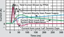
Since FPGAs are digital devices, they have potentially large load-current transient spikes. Most FPGA manufacturers provide guidance to the system designer in selecting the decoupling capacitors for each power rail to minimise load transient effects, such as the power rail being pulled below the -5% tolerance. Figure 10 shows the various sources of steady-state and transient currents on a power rail.
Various 'fast-transient-response' point-of-load converters are available. It is generally recommended that a point-of-load converter with a fast transient response be used on fast-switching power rails. Most linear regulators use their output capacitance to set the dominant pole of their feedback loop so that they remain stable with large capacitive loads. However, most switching converters that were optimised for minimal output ripple and/or fast transient response have feedback loops that were compensated to operate within a bounded range of output capacitance and related ESR. So, when stabilising the feedback loop of the point-of-load switching converter, the system designer must include the decoupling capacitors as part of the converter's output capacitance.
Conclusion
The secret to successful power-up of FPGAs is to use soft starting and sequencing. The amount of load current and the related power dissipation in the point-of-load converter are the determining factors for choosing a DC-DC converter. Linear regulators are appropriate for higher FPGA core voltages but require additional soft-start circuitry. Lower core voltages require switching regulators due to power dissipation limitations in linear regulators. Switching regulators typically have built-in soft start and do not require additional circuitry.


© Technews Publishing (Pty) Ltd | All Rights Reserved
 printer friendly version