
Ref: z2708352m
This article describes how to design a clock oscillator circuit by using Murata's Ceralock (resonators), how to get the optimum circuit constant of each component, and also, it discusses the differences between Ceralock and a traditional quartz crystal resonator.
To begin with we examine the differences between a Ceralock and a quartz crystal resonator. Figure 1 shows the typical frequency characteristics of phase and impedance for Ceralock.
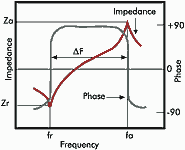
Ceralock is inductive in the frequency range between the resonant frequency (fr) of the minimum impedance value and the anti-resonant frequency (fa) of the maximum impedance value. Outside these ranges it is capacitive. When using Ceralock to construct an oscillator circuit, the inductive characteristics between fr and fa are used instead of L in the LC oscillator circuit.
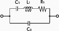
Figure 2 shows the equivalent circuit of either Ceralock or quartz crystal resonators. The circuit is a series-parallel resonator circuit that comprises the equivalent resistance R1, the equivalent inductance L1, the equivalent capacitance C1 and the capacitance between the electrodes C0. Table 1 shows typical values for each circuit element of both Ceralock and quartz crystal resonators. Figure 3 shows the analogy between the electrical equation of motion and the mechanical equation of motion.
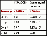
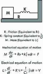
As shown in Table 1, Ceralock has a smaller value of L1 which is equivalent to mass M of the mechanical equation of motion, and a larger value of C1 which is equivalent to the reciprocal of the spring constant k. This means that the Ceralock has faster rise time than the quartz crystal resonator.
While the quartz crystal oscillator takes a few milliseconds to start up, Ceralock oscillators take only a few tens of microseconds. Because of shorter start up time, Ceralock is suitable for use in such equipment that requires frequent start-up or power-on from a sleep state. This is particularly the case for microcomputers that use energy saving standby modes, because quick rise times result in faster computing.
Selection of constants for the oscillator circuit
Usually, a CMOS inverter is used for an oscillator circuit that uses either Ceralock or quartz crystal resonators. However, as Table 1 shows, the equivalent circuit constant values differ very much from each other and one must be careful to design a stable oscillator. Also, the optimum circuit constant for each component differs depending on the combinations of the IC and Ceralock. Generally, the optimum value for each component is assumed to be the circuit constant when the oscillation voltage at the IC's input and output terminals becomes the maximum value within the IC's drive voltage rating.
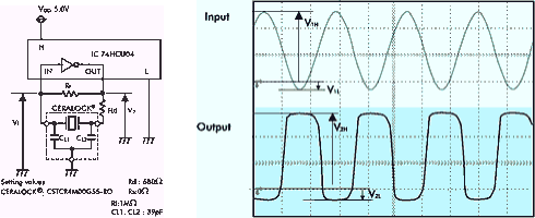
The following explains the key points to note when selecting the optimum circuit constants for each component. This is demonstrated by showing the oscillation voltage and waveform (Figure 4b) of the reference circuit (Figure 4a). Figure 4 to Figure 6 show the peak and bottom of the oscillation wave form, where V1H, V1L are the measured voltages at the IC's input terminals and V2H, V2L the measured voltages at the output terminals.
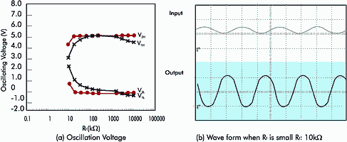
* Feedback resistance Rf: The feedback resistance Rf serves as a bias resistance to operate the CMOS inverter as an inverting amplifier. Figure 5a shows the changes of the oscillation voltage when the feedback resistance Rf is varied. When Rf gets too small, the gain of the amplifier decreases and consequently the oscillation voltage decreases (Figure 5b). When Rf gets too large, and the insulation resistance at the IC's input decreases, the oscillation may become unstable or stop altogether. Normally about one MΩ is the recommended value for Rf when using Ceralock, if the IC has five MΩ or more of Rf built in.
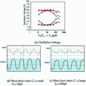
* Load capacitance: CL (CL1 = CL2): Figure 6a shows the change of oscillation voltage when load capacitance CL is varied. CL is an important parameter that affects the stability and frequency of oscillation. Load capacitance must be carefully selected to match the IC as, when CL gets too small, the waveform becomes distorted (Figure 6b) and oscillation becomes unstable. When CL gets too large, the oscillation voltage decreases (Figure 6c) and the oscillation may well stop altogether.
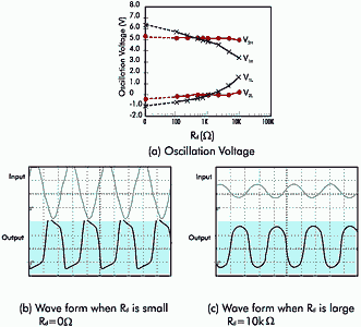
* Damping resistance Rd: Figure 7(a) shows the change of the oscillation voltage when damping resistance Rd is varied. There are many cases where an overshoot or undershoot of oscillation voltage is generated when the Rd is zero (Figure 7b). This can be avoided by adding Rd (Figure 7c). Also, Rd forms a low pass filter with load capacitance CL2, and makes the loop gain smaller at higher frequency and suppresses unwanted oscillation in the high frequency range. Another role of Rd is to reduce the current consumption and noise radiation.
Causes of the change of oscillation frequency
When using Ceralock for applications that requires a precise oscillation frequency, all the factors that cause frequency change must be taken into consideration and the influence of these carefully evaluated. Generally there are two major factors causing the frequency change. These are the resonant frequency change of Ceralock itself and the change of load capacitance CL1 and CL2.
The causes of the resonant frequency change of Ceralock can be the initial deviation of resonant frequency, temperature characteristics, long-term ageing characteristics and soldering heat characteristics of Ceralock. The change of load capacitance CL1 and CL2, can be caused by the lC's input and output capacitance or the stray capacitance of the circuit board as shown in Figure 8.
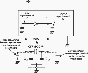
It is important to consider how much oscillation frequency is affected by these factors. The amount of frequency change caused by stray capacitance of the lC's input and output terminals can be checked by assembling circuits using a variety of IC samples. The stray capacitance of the circuit board varies according to the length and the width of land figure, number of layers, and material of the circuit board. The frequency change should be estimated through measurement of the stray capacitance and computer simulation.
Many of the important considerations in using Ceralock for an oscillation circuit have been described in this article. Other than the above, Murata offers evaluation reports at web site at www.murata.com for various ICs and their reference circuits so that one can obtain the optimum operation.
© Technews Publishing (Pty) Ltd | All Rights Reserved