


Cooling fans are an important part of thermal management for high-powered chips and systems. Unfortunately, their use can sometimes raise a system's acoustic noise level to the point where it is objectionable.
By measuring temperature and adjusting fan speed accordingly, a fan's speed and noise level can be minimised when temperature is low, but increased under worst-case conditions to prevent damage. This article describes two techniques for automatically controlling a cooling fan's speed.
High-speed chips tend to run hot. As they get faster, they get hotter. New generation high-speed digital chips are made with smaller processes that allow the supply voltage to be reduced, which helps, but the number of transistors increases faster than the supply voltage decreases. Power levels, therefore, continue to rise.
As chip temperature increases, performance can suffer. Parameters shift, maximum operating frequencies decrease, and timing can fall out of specification. From the user's point of view, the product is no longer operating properly when this occurs. The first reason for cooling high-speed chips, therefore, is to maintain good performance for the longest possible operating time and over the widest possible range of environmental conditions. The maximum allowable temperature for a high speed chip to meet its parametric specifications depends on the process and how the chip is designed (ie, how 'close to the edge' the chip is operating), among other factors. Typical maximum die temperature values range from +90°C to +130°C.
Beyond the point where performance degradation begins, excessive die temperature causes catastrophic damage. The maximum die temperature limit is usually well over +120°C and depends on such factors as process, package, and duration of high-temperature conditions. High-speed chips are, therefore, cooled to avoid reaching such temperatures.
Techniques
A single cooling technique is rarely used. Instead, combinations of techniques are generally necessary to ensure high performance and continued reliability. Heatsinks, heat pipes, fans and clock throttling are commonly employed. The last two, fans and clock throttling, can help solve the heat problem, but introduce their own problems.
Fans can dramatically reduce the temperature of a high-speed chip, but they also generate much acoustic noise. This noise is annoying to some consumers and is also becoming a target of government agencies concerned about the long-term effects of noise in the workplace. Fan noise can be reduced significantly by varying the fan's speed based on temperature; the fan can turn slowly (and very quietly) when temperature is low, and can speed up as temperature increases.
Clock throttling - reducing clock speed to reduce power dissipation - works by reducing system performance. When throttling the clock, the system continues to function, but at a reduced speed. Clearly, in high-performance systems, throttling should be done only when it is absolutely necessary - that is, when the temperature reaches the point where functionality is about to be lost.
Temperature sensing
Controlling fan speed or clock throttling based on temperature requires that the temperature of the high-speed chip is measured first. This can be done by placing a temperature sensor close to the target chip - either directly next to it or, in some cases, under it or on the heatsink. The temperature measured this way corresponds to that of the high-speed chip, but can be significantly lower (up to around 30°), and the difference between measured temperature and die temperature increases as the power dissipation increases. Therefore, the temperature of the circuit board or heat sink must be correlated to the die temperature of the high-speed chip.
A better alternative is possible with a number of high-speed chips. Many CPUs, graphics chips, FPGAs, and other high-speed ICs include a 'thermal diode', which is actually a diode-connected bipolar transistor, on the die. Using a remote-diode temperature sensor connected to this thermal diode, the temperature of the high-speed IC's die can be directly measured with excellent accuracy. This not only eliminates the large temperature gradients involved in measuring temperature outside the target IC's package, but it also eliminates the long thermal time constants, from several seconds to minutes, that cause delays in responding to die temperature changes.
The need for fan control forces the designer to make several key choices. The first choice is the method of adjusting the fan's speed. A common method of adjusting the speed of a brushless DC fan is to regulate the power-supply voltage of the fan. This works well for power-supply voltages as low as about 40% of the nominal value. There is a drawback: If the power-supply voltage is varied using a linear pass device, the efficiency is poor. Better efficiency can be obtained using a switch-mode power supply for the fan, but this increases cost and component count.
Speed control
Another popular fan-speed control technique is to power the fan with a low-frequency PWM signal, usually in the range of about 30 Hz, whose duty cycle is varied to adjust the fan's speed. This is inexpensive because a single, small pass transistor can be used. It is efficient because the pass transistor is used as a switch. A disadvantage of this approach, however, is that it can make the fan somewhat noisier because of the pulsed nature of the power supply. The PWM waveform's fast edges cause the fan's mechanical structure to move (somewhat like a badly designed loudspeaker), which can easily be audible.
Another fan-control design choice is whether the fan's speed is measured as part of the control scheme. In addition to power and ground, many fans are available with a third wire that provides a 'tachometer' signal to the fan-control circuitry. The tachometer output produces a specified number of pulses (two pulses, for example) for each revolution of the fan. Some fan-control circuits use this tachometer waveform as a feedback signal that allows the fan's voltage or PWM duty cycle to be adjusted to give a desired RPM. A simpler approach ignores any tachometer signal and simply adjusts the fan's drive to speed up or slow down with no speed feedback. Speed control using this method is less precise, but cost is lower and at least one feedback loop is removed, simplifying the control system.
In some systems, it is important to limit the change rate of the fan speed. This is most critical when the system is in close proximity to users. Simply switching a fan on and off or changing speed immediately as temperature changes is acceptable in some environments. When users are nearby, however, sudden changes in fan noise are apparent and annoying. Limiting the rate of change of the fan's drive signal to an acceptable value (eg, 1% per second) ensures that the acoustic effects of fan control are minimised. The fan speed still changes, but it does so without attracting attention.
The fan-control profile is another important design variable. Typically, the fan is off below a specific threshold temperature and then begins to spin at a slow rate (for example, 40% of full speed) once the threshold is exceeded. As temperature increases, the fan's drive increases linearly with temperature until it reaches 100% drive. The best slope depends on system requirements. A more rapid slope results in somewhat more consistent chip temperature, but fan speed has more variation as power dissipation changes from one moment to the next. If highest performance is the goal, the starting temperature and the slope should be chosen so that the fan reaches full speed before the die temperature is high enough to initiate clock throttling.
Implementation
Implementing fan-control circuitry can be done in several ways. A variety of remote temperature sensors with up to five sensing channels is available that can detect the die temperature of the high-speed chip and transmit temperature data to a micro-controller. Fan speed regulators with multiple channels of fan tachometer monitoring can provide reliable control of fan RPM or supply voltage based on commands from an external microcontroller. For low cost and simple implementation, ICs are available with temperature sensing and automatic fan control included in a single package. Sensor/controllers also normally include overtemperature detection for clock throttling and system shutdown, thereby protecting the high-speed chips from catastrophic failure due to overheating.
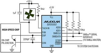
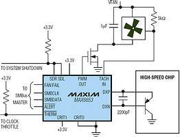
Examples of two such ICs, one with DC drive and one with PWM drive, are shown in Figures 1 and 2. The IC in Figure 1 senses remote temperature and controls fan speed based on that temperature. It produces a DC supply voltage for the fan through an internal power transistor. Figure 2 shows an IC that performs a similar function, but drives the fan with a PWM waveform through an external pass transistor. Both include complete thermal fault monitoring with overtemperature outputs, which can be used to shut down the system if the high-speed chip gets too hot.
| Tel: | +27 11 608 0070 |
| Email: | [email protected] |
| www: | www.cstelectronics.co.za |
| Articles: | More information and articles about CST Electronics |


© Technews Publishing (Pty) Ltd | All Rights Reserved
 printer friendly version