After determining the basic wireless system requirements, the wireless system designer must then choose a radio IC. Many different transceiver architectures have been used in the past along with many different modulation types, but which transceiver IC is best for the application can sometimes be a difficult decision. Part III of this series takes a look at some transceiver architectures.
Figure 1 shows the classic 'double-conversion heterodyne' architecture used in nearly all high-performance radios. Its principle of operation is to downconvert the incoming signal in two steps so that the difficult filtering and amplification is performed at the lower IF frequencies. It has excellent sensitivity, excellent rejection of interferers but needs many offchip components and generally not used in highly integrated applications.

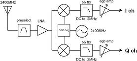
Figure 2 shows the more advanced 'direct conversion' (also called zero-IF) architecture. Note that the input signal is now converted directly to baseband so there is no image rejection filtering required at the front-end. All channel filtering and amplification is now done at baseband, which makes this approach quite attractive to IC designers since very few off-chip components are necessary. Direct conversion architectures have been around for a while but past problems with DC offsets, LO leakage, etc, have slowed their adoption. Recent advances seem to be overcoming these problems and but for now the primary users of this architecture remain the more complex I/Q modulation approaches (like 802.11).

Figure 3 shows a simplified diagram of a 'low-IF' architecture which takes advantage of the benefits of baseband amplification and filtering (found in the ZIF architecture) but eliminates the DC offset problem by converting to a low IF frequency (instead of directly to baseband) which is AC coupled. Unfortunately this places the (undesirable) image frequency very close to the desired signal which implies critical RF front-end filtering. To obviate this the design implements an integrated image-reject mixer by using I/Q mixing followed by a summer, effectively cancelling the image frequency instead of using off-chip components to filter it. This approach has proven to be very popular in low-cost highly integrated transceivers (including Bluetooth) and is the recommended receiver architecture for the applications discussed in this article.

After a suitable receiver architecture is chosen the designer must investigate the many different ways to implement the transmitter side of the radio.
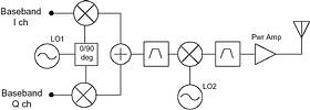
Figure 4 shows a common 'indirect I/Q upconversion' transmitter. The key benefit of this approach is that the use of an upconversion architecture minimises transmitter instability commonly seen when the VCO and the Tx signals are at the same frequency. This is caused by the high-power Tx signal leaking back into the highly sensitive VCO circuits. Unfortunately this approach relies on the baseband circuitry to generate complex gain/phase matched IF signals necessary for such modulation approaches as QPSK, etc.

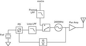
Figure 5 illustrates simple 'direct VCO modulation'. This approach is commonly used to implement simple phase/frequency modulation schemes such as FSK/PSK. Two variations have been implemented. The first is open-loop and the second is closed-loop. In open-loop implementations the PLL is first locked onto the desired channel frequency and then the loop opened to allow the data to directly modulate the carrier frequency (ie FSK modulation).

The limitation of this approach is that the carrier centre frequency tends to drift with time so Tx packet lengths are limited. The second approach solves this problem by applying the modulation while the loop remains closed. Closed-loop modulation allows much longer Tx packet lengths to be transmitted and yields more accurate carrier frequencies and modulation. Today's simple data receivers almost always use direct VCO modulation to implement simple non-coherent FSK modulation schemes.
So how does a systems engineer go about choosing the right solution? The good news is that with today's integrated transceivers most of the difficult decisions have already been made and implemented 'on chip'. The design process is then reduced to comparing the desired system requirements discussed in Part II to the transceiver datasheet and any accompanying application notes.
In Part IV of this series to follow, we will discuss the performance and cost trade-offs inherent in the choice of wireless protocol.
For more information contact Kevin Jurrius, Components & System Design, 011 979 4274, [email protected]

© Technews Publishing (Pty) Ltd | All Rights Reserved