
Temperature is such an important element in the use of electrolytic capacitors (elcaps) that close attention has to be paid to all the factors that influence the temperature of the device. This article from BCcomponents looks at these factors and provides advice on calculating elcap lifetimes in order to select the correct capacitors for power supplies.
Ambient temperature and expected ripple current both contribute to the lifetime of the devices which of course has to be matched with the lifetime of the supply. Outside of the temperature factors there are always the mechanical characteristics, minimum capacitance and the maximum equivalent series resistor (ESR) of the device to be considered.
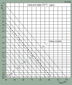
In a power supply it is not possible to consider only ambient temperature for lifetime calculations as factors such as self-heating become a significant part of the calculations. In order to calculate lifetime, BCcomponents developed a 'lifetime nomogram', using a parameter linked to ohmic losses (IA/IR) and the ambient temperature, to calculate a multiplier that determines the lifetime of the device.
The nomogram in Figure 1 defines ambient temperature as 'the temperature of the air, in still air conditions, at such a distance from the elcap that the effect of dissipation is negligible'. But in a densely packed power supply, measuring the ambient temperature is difficult and as a first approximation it is possible to use the temperature of the case.

The factor IA/IR is the ratio of the equivalent application ripple current to the rated ripple current. If this ratio is greater than one, the application causes significant heating of the elcap.
IR (the rated ripple current) shows how well the elcap can handle the ripple current running through it during charging and discharging, that is to say how much heat is generated and how well the elcap can dissipate it. For BCcomponents' capacitors, the rated ripple currents at the defined frequencies of 100 and 120 Hz or 100 kHz result in a temperature rise in the elcap of 5 to 10°C.
IA (the equivalent application ripple current) is a current at the same frequency as IR, which causes the same self-heating as the actual ripple current in the application. This is similar to the definition of the RMS voltage of a waveform: 'The RMS voltage of a waveform is that DC voltage which generates the same heat in a resistor as the waveform itself.' The only difference is that it is now the heat generated in the elcap that matters.
If the application ripple current has the same frequency as defined for the rated ripple current, the relation is easy. The equivalent application ripple current IA is equal to the application ripple current. If the application ripple current has a different frequency or has more frequency components, the calculation becomes more difficult. It requires knowledge of the RMS values of the individual frequency components of the application ripple current and involves correction factors Kfn. These correction factors are provided for each series and allow for calculation of the frequency dependency of the self-heating. The following formula shows how the equivalent application ripple current IA can be calculated if the application ripple current has a different frequency (n = 1) or more frequency components (n > 1):

The RMS values of the ripple currents at the different frequencies can be obtained from a circuit simulation, from direct measurements with an RMS meter with sufficient bandwidth, or an oscilloscope. Splitting the main frequency components might be accomplished by measuring in the right current path or by introducing a simple RC filter between the measurement point and the measuring instrument.
When using an oscilloscope for RMS current measurements, there are a number of factors to consider. The first is how the oscilloscope 'measures' the RMS value. Contrary to RMS meters, the oscilloscope does not measure the heat generated by the waveform but calculates the heat that would be generated from the measured voltage samples. If the sampling rate is less than two times the frequency of the highest frequency components, they are not fully captured and their contribution to the RMS value is calculated incorrectly. If the measured voltage samples do not contain at least one period of the lowest frequency, the same applies. If both high and low frequency components are present in the signal, a long record length is required to fulfil both requirements.
The second factor to consider is how the signal is picked up. A current probe hardly changes the ripple current in the circuit but it usually has a limited lower bandwidth and may not be able to measure the 100 Hz components correctly. An alternative is to place a low inductance surface mount resistor in series with the capacitor and soldering a coaxial cable directly over it to link to the oscilloscope with minimal noise picked up. The value of the resistor should be less than the warm ESR of the capacitor, 10 mOhm being a good value. Care must be taken to ensure that the ground of the oscilloscope is earthed to avoid a possible short circuit. It is also wise to use an isolation transformer to separate out the circuit from the mains.
Finally, it is a good idea to check that the sum of the RMS values of all the main frequency components add up to a value close to the RMS value of the full signal in the time domain. If this is not the case, then all the components can be multiplied by the ratio of the two to correct for this difference. Keep in mind that the following equation must be used to add up the RMS values of the frequency components:
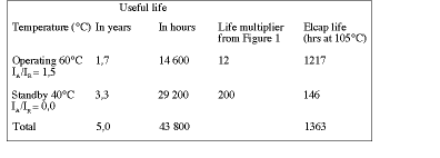
An example of how to use the nomogram can be shown with a power supply in a TV set which is expected to operate for eight hours a day for five years. The ambient air temperature inside the set is 40°C when not in operation and 60°C when operating. In operation, the ripple current is 50% higher than the rated value, ie IA/IR = 1,5. For a radial 105°C type elcap with the lifetime nomogram in Figure 1, Table 1 shows that the elcap must have a useful life of over 1363 hours at 105°C.

Apart from lifetime and operating temperature, other parameters should be considered as well. An obvious one is the capacitance of the elcap. For DC decoupling and filtering, the equation:
applies. This is relatively simple but does not take into account the effect of the ESR with regards to low temperatures or high frequencies. For buffering and energy storage the equation:
can be used. This equation applies to the calculation of the minimum capacitance for the mains input buffer of a typical power supply. It is important to remember that the minimum capacitance must be met at the end of the useful life, which for some elcap series is when the capacitance has dropped by 30%.
Another parameter is equivalent series resistance or ESR. The main effect of the ESR is self-heating from ripple currents, but it can cause another effect, particularly for frequencies greater than 10 kHz, where the ESR is the dominant contribution to the impedance of the capacitor.
If the elcap is charged by low duty cycle, high current pulse (as is the case for the output capacitor of a flyback supply), the ripple caused by the voltage drop over the ESR can be higher than the ripple caused by the charging and discharging of the capacitor. This means that the maximum ripple allowed on the output voltage then determines the required maximum ESR for the device. As the ESR is temperature dependent and will drop as the device warms up, the ripple voltage will decrease as the supply warms up.
The lowest ESR in a design is obtained using an elcap from a low ESR series, having a thin long case size for low foil resistance and a large size with more foil in contact with paper and electrolyte. As there are usually only two connections to the foil in an elcap, many smaller capacitors in parallel will show lower high frequency ESR than a single large one.
In conclusion, alongside the standard considerations of capacitance, operating voltage and size, it is also vital to consider temperature, ripple current, application life and ESR in determining the most appropriate electrolytic capacitor for use in a power supply design.
| Tel: | +27 11 458 9000 |
| Email: | [email protected] |
| www: | www.electrocomp.co.za |
| Articles: | More information and articles about Electrocomp |

© Technews Publishing (Pty) Ltd | All Rights Reserved