With Power over Ethernet (PoE) being a popular and mature technology, it’s no surprise that power sourcing equipment (PSE) and powered device (PD) developers are eager to jump onto the next IEEE bandwagon and start delivering higher levels of power down Ethernet cables.
However, as with many industry standards, IEEE PoE standards often finalise much later than is needed by the market. The latest timeline from the IEEE PoE task force shows the 71 W 802.3bt standard won’t be ready until early 2018. That’s a long time to wait in technology years, which can easily translate to missed business opportunities or markets.
So, what are PSE and PD developers supposed to do in this case? Why, design and manufacture now of course! Developers who want to be first to the 802.3bt market have Linear Technology’s LT4295 IEEE 802.3bt PD controller available to them today, compliant to draft 2.0 of the standard.
More power, more potential
Not surprisingly, the main focus for the IEEE PoE task force and developers has been how much power is ultimately provided to PDs. In 2003, the IEEE PoE task force established in the original IEEE 802.3af PoE standard that ~13 Wwould be available at the PD input’s RJ-45 jack. Since then, the market has continued to demand more power. So, in 2009, the IEEE PoE task force revised the standard and released IEEE 802.3at (also known as PoE+), which increased the maximum PD power level to 25,5 W.
Fast forward to today and it is expected that the current revision, IEEE 802.3bt draft 2.0 (also known as PoE++ or 4PPoE), will provide PDs with up to 71 W of power. With more power, developers can easily add more features and upgrade existing products. Take the security camera as an example of an application that has evolved throughout the PoE years. With only 13 W available, the first PoE-powered security cameras were simple stationary units. However, when 25,5 W was allocated by 802.3at, extra power was available to drive multiple embedded motors which provided security cameras with pan, tilt and zoom capabilities. Now, with 802.3bt’s 71 W to tap into, pan-tilt-zoom security cameras can also integrate fans and heating elements to support operation at extreme temperatures.
For some, higher PoE power levels may unlock distinctly new markets. For example, a traditional LED lighting manufacturer, who only produced ceiling units controlled by wall switches, but can now produce PoE-enabled units that will help pave the way for smart homes or buildings. Whether more power evolves or revolutionises the end product, there is clearly more market potential with each iteration of the PoE standard.
Changes to the PSE-PD link
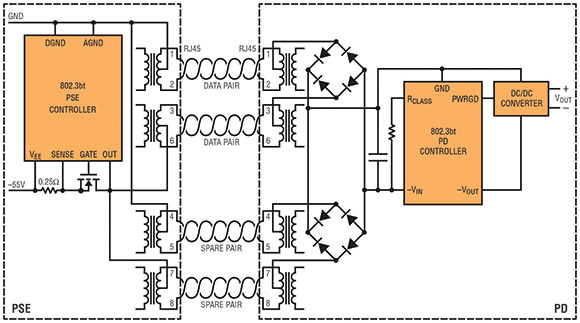
As you might have already guessed, 4PPoE stands for ‘4-pair PoE’, since 802.3bt takes advantage of all four twisted pairs in the Ethernet cable to transmit power up to 100 m; in older PoE standards, 4-pair power delivery was non-compliant. See Figure 1 for a typical block diagram of an IEEE 802.3bt PSE-PD link.

Cabling requirements are still up in the air, but cabling committees and manufacturers are guessing that 802.3bt will require at least Category 5E cabling in order to support the increased power levels while operating with 10GBASE-T (10 Gbps Ethernet data speed). In any case, because we are now reaching the current handling limitations of the Ethernet cable, you may have to pay attention to cabling-system performance characteristics that were previously ignored.
802.3bt introduces two new PD topologies: single-signature and dual-signature. That is, a single-signature PD is an 802.3bt PD that shares the same detection signature, classification signature and maintain power signature (MPS) between both pairsets, whereas a dual-signature PD is an 802.3bt PD that has independent signatures between both pairsets.
New 802.3bt designs will, no doubt, gravitate towards the simpler and more cost-effective single-signature topology, which only calls for a single PD interface. Dual-signature PDs require two parallel PD interfaces, one for each pairset, where the power from two PSEs is summed up after each PD interface. Essentially, the dual-signature topology uses, for example, two 25,5 W PDs to make a single 51 W PD – a complex solution that can cost twice as much as a single-signature 51 W PD.
The 802.3bt detection process has been expanded to be able to differentiate not only that the connected PD is an 802.3-compliant PD, but also to determine whether a single- or dual-signature PD is connected. As such, detection is now augmented by a connection check to determine the single- or dual-signature PD configuration.

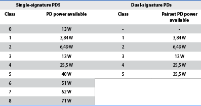
802.3bt introduces four new high-power PD classes, bringing the total number of single-signature classes to nine as shown in Table 1. Classes 5 through 8 are new to PoE and translate to PD power levels ranging from 40,0 W to 71,0 W. PSEs still have their choice of using the physical layer (i.e. 5-event classification for 71 W) or data link layer (i.e. link layer discovery protocol, LLDP) to classify PDs, and PDs still need to be able to support both classification schemes in order to be compliant.
802.3bt PDs may also implement an optional extension of the physical layer classification, known as Autoclass, where an 802.3bt PSE measures the actual maximum power draw of a connected PD. This handy power management feature allows, for example, a PSE to allocate leftover power to additional light bulbs if it knows that a particular bulb will draw less than its class power.
For those of you with PDs that require a deep sleep mode, you’ll be happy to know that 802.3bt introduced a lower power version of the maintain power signature (MPS), referred to as Low MPS. Under the older PoE standards, a PD has to sink a small DC current at a 32% duty cycle in order to tell the PSE to keep the PD on. However, this relatively high duty cycle can quickly become a burden in some applications, such as when you consider new energy efficient building standards. 802.3bt PDs are now only required to maintain a small DC current at a ~2% duty cycle, drastically reducing the standby current.
Table 2 summarises the 802.3bt PD types and features. You may already be familiar with Type 1 and Type 2 PDs, which were introduced by 802.3af and 802.3at respectively and typically map to one or more unique classes (power levels). 802.3bt’s new Type 3 and Type 4 PDs, however, are not as straightforward.

As you can see from the ‘PD Class’ column, with the exception of Class 0, Type 3 PDs cover and extend the classes in Type 1 and Type 2 PDs. Similarly, Class 5 is employed by both Type 3 single-signature and Type 4 dual-signature PDs. Moreover, from Figure 2, a Class 5 single-signature PD is only allocated 40 W, while a Class 5 dual-signature PD is allocated 2 x 35,5 W; to make things worse in dual-signature PDs, because each pairset operates independently, each pairset can be of different class – for example, Class 1 (3,84 W) on the first pairset and Class 2 (6,49 W) on the second pairset makes for a dual-signature Class 1.2 (10,3 W) PD.
With all of this class overlap and proliferation of non-standard power levels by dual-signature PDs, it becomes important that developers and users alike no longer synonymise PD types with PD classes nor PD classes with PD power levels. Instead, it would be in everyone’s best interest to explicitly identify a PD’s signature topology and class, with a cautious look at what is really meant by a PD’s ‘type.’
It goes without saying that 802.3bt is backward compatible with 802.3at and 802.3af. A lower power 802.3at or 802.3af PD can connect to a higher power 802.3bt PSE without any issues. And, when the table has turned and a higher power 802.3bt PD is connected to a lower power 802.3at or 802.3af PSE, the PD just needs to be able to operate in the respective lower power state – this is referred to as demotion. If a PD ignores demotion and operates at its highest power state, the power-hungry PD will cause the PSE to repeatedly turn on, hit its current limit, then turn off – in effect, motor boating the PSE. For this reason, demotion is required by both 802.3at and 802.3bt, but is unfortunately overlooked in many implementations.
Squeezing every Watt out
The most important aspects of a high power PD design are generally cost and efficiency, which are largely driven by the ICs chosen to implement the PD interface. In addition, developers with space constrained designs are painfully aware of how limiting a PD’s size only becomes more of a challenge as higher power levels call for larger discrete components and larger heatsinks. For this reason, Linear Technology provides three ICs that are specifically designed to maximise 802.3bt PD performance and, perhaps more importantly, simplify the designer’s job.
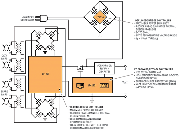
Figure 2 shows a simplified block diagram of a high efficiency single-signature 802.3bt PD interface with an auxiliary input. This solution provides an end-to-end (RJ-45 input to PD load) efficiency of greater than 94% and operates within the -40°C to 125°C temperature range. The LT4321, shown on the RJ-45 interface in Figure 2, is an ideal diode bridge controller that replaces the two diode bridge rectifiers (Figure 1). The LT4321 uses low-loss N-channel MOSFET bridges to simultaneously increase the PD’s available power and reduce heat dissipation.

802.3bt requires PDs to accept DC supply voltages of any polarity over their Ethernet inputs, so the LT4321 smoothly rectifies and combines power from the data and spare pairs into a single, polarity-correct supply output. Overall circuit size and cost are reduced as the enhanced power efficiency practically eliminates heatsinking requirements, and power savings of 10x or more enable PDs to stay within classification power budgets or add additional functionality.
Following the ideal diode bridge controller in Figure 2 is the brains of the PD interface – the LT4295 is an 802.3bt compliant PD interface controller that integrates a high efficiency forward or no-opto flyback controller. The LT4295 supports all nine PD classes and all four PD types with an integrated 25 kΩ signature resistor, up to 5-event classification sensing, and a single-signature topology.
Aside from providing more PD power, what gives the LT4295 an edge over traditional PD controllers is its use of an external power MOSFET to drastically reduce overall PD heat dissipation and maximise power efficiency, which, again, becomes more important at 802.3bt’s higher power levels. This novel approach allows you to size the MOSFET to your application’s specific heating and efficiency requirements, enabling the use of MOSFETs with as low as 30 m of on-resistance.
If 802.3bt’s 71,0 W leaves you thirsting for more, seek out Linear Technology’s family of LTPoE++ PSE and PD controllers, which provide power levels up to 90 W. The LTPoE++ standard employs a similar classification scheme to 802.3bt that enables LTPoE++ PSE controllers and LTPoE++ PD controllers to reliably communicate with one another while maintaining interoperability with 802.3at and 802.3af equipment. With just a single cable, you just plug-and-play an LTPoE++ PD into an LTPoE++ PSE – all of the hand shaking is automatically handled via hardware, no software required.
Finally, for those of you with 802.3bt PDs that need to be able to support an auxiliary supply, where the PD can be optionally powered by a power adaptor in addition to PoE, the LT4320, shown at the top of Figure 2, is a 9 V to 72 V ideal diode bridge controller that replaces each of the four diodes in a full wave bridge rectifier with a low loss N-channel MOSFET to significantly reduce the power dissipation and increase available voltage. Power supply and wall wart sizes can be reduced as the enhanced power efficiency eliminates bulky and costly heatsinks. Low voltage applications can also benefit from the extra margin afforded by saving almost two full diode drops (~1,2 V, which is 10% at 12 V) inherent in hot-running diode bridges, increasing the application headroom.
Conclusion
IEEE’s 802.3bt is far from being finalised, but developers can confidently go to market now with major aspects of the standard starting to settle down. 802.3bt’s PD types, topologies and classes support higher power levels up to 71,0 W, while a new MPS signature supports lower standby power when PDs are asleep.
As PoE pioneers and active members of the IEEE task force, Linear Technology continues to be at the forefront of PoE with released 802.3bt and LTPoE++ PD and PSE controllers. It’s up to savvy, well-informed developers to capitalise on these ICs – that simplify designs, maximise power efficiency, minimise size and reduce total BOM costs – and be the first to the 802.3bt market.
For more information contact Conrad Coetzee, Arrow Altech Distribution, +27 (0)11 923 9600, [email protected], www.arrow.altech.co.za
| Tel: | +27 11 923 9600 |
| Email: | [email protected] |
| www: | www.altronarrow.com |
| Articles: | More information and articles about Altron Arrow |

© Technews Publishing (Pty) Ltd | All Rights Reserved