


Poor grounding not only increases the risk of equipment failure; it is dangerous. Facilities need to have adequately grounded electrical systems so that in the event of a lightning strike, or utility overvoltage, current will find a safe path to earth.
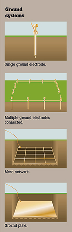
Simple grounding systems consist of a single electrode driven into the ground. This is the most common form of grounding and can be found outside homes or places of business.
Complex grounding systems consist of multiple ground rods connected in a mesh or grid network together with ground plates and ground loops. These systems are typically installed at power-generating substations, central offices, and cell tower sites.
Locations of resistances
1.The ground electrode and its connection.The resistance of the ground electrode and its connection is generally very low. Ground rods are generally made of highly conductive/low-resistance material such as steel or copper.
2.The contact resistance of the surrounding earth to the electrode. The National Institute of Standards has shown this resistance to be almost negligible, provided that the ground electrode is free of paint, grease, etc., and that the ground electrode is in firm contact with the earth.
3.The resistance of the surrounding body of earth. The ground electrode is surrounded by earth which conceptually is made up of concentric shells all having the same thickness. Those shells closest to the ground electrode have the smallest amount of area, resulting in the greatest degree of resistance. Each subsequent shell incorporates a greater area resulting in lower resistance. This finally reaches a point where the additional shells offer little resistance to the ground surrounding the ground electrode.
What affects the grounding resistance?
The NEC code (1987, 250-83-3) requires a minimum ground electrode length of 2,5 metres to be in contact with soil. Besides that measurement, there are four variables that need to be taken into account that affect the resistance of a ground system:
• Length/depth of the ground electrode.
• Diameter of the ground electrode.
• Number of ground electrodes.
• Ground system design.
Length/depth of the ground electrode
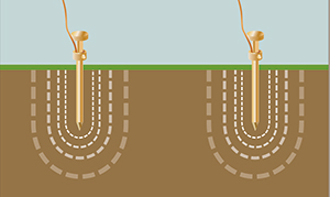
One very effective way of lowering ground resistance is to drive ground electrodes deeper. Soil is not consistent in its resistivity and can be highly unpredictable. It is critical when installing the ground electrode, that it is below the frost line. This is done so that the resistance to the ground will not be greatly influenced by the freezing of the surrounding soil.
Generally, by doubling the length of the ground electrode, you can reduce the resistance level by an additional 40%. There are occasions where it is physically impossible to drive ground rods deeper – areas that are composed of rock, granite, etc. In these instances, alternative methods, including grounding cement, are viable.
Diameter of the ground electrode
Increasing the diameter of the ground electrode has very little effect on lowering the resistance. For example, the diameter of a ground electrode could be doubled and the resistance would only decrease by 10%.
Number of ground electrodes
Another way to lower ground resistance is to use multiple ground electrodes. In this design, more than one electrode is driven into the ground and connected in parallel to lower the resistance. For additional electrodes to be effective, the spacing of additional rods needs to be at least equal to the depth of the driven rod. Without proper spacing of the ground electrodes, their spheres of influence will intersect, and the resistance will not be lowered.
Ground system design
Complex networks dramatically increase the amount of contact with the surrounding earth and lower ground resistances.
| Tel: | +27 10 595 1821 |
| Email: | [email protected] |
| www: | www.comtest.co.za |
| Articles: | More information and articles about Comtest |


© Technews Publishing (Pty) Ltd | All Rights Reserved
 printer friendly version