The Internet of Things (IoT) revolution has allowed for a paradigm shift in the way healthcare providers leverage technology to provide their patients with real-time care. Today, remote patient monitoring is an area where new medical devices are changing the way doctors interact with their patients.
Smaller ICs and wireless communication have enabled decades-old devices to be updated to enhanced functional form factors that increase patient adherence and outcomes. Replacing clunky Holter devices of the past, current remote patient monitoring (RPM) patches include a variety of sensors that gather heart rate, temperature and accelerometer data. These patches transmit patient data to the cloud, allowing patients and doctors to access the data in real time.
While these devices are increasing the ability for doctors to provide better care, they pose challenges for power supply designers who must balance system performance and battery life requirements. The challenges increase further as second-generation patches adopt multimodal sensing to improve accuracy and efficacy, which, in turn, increases the demands on the power supply.

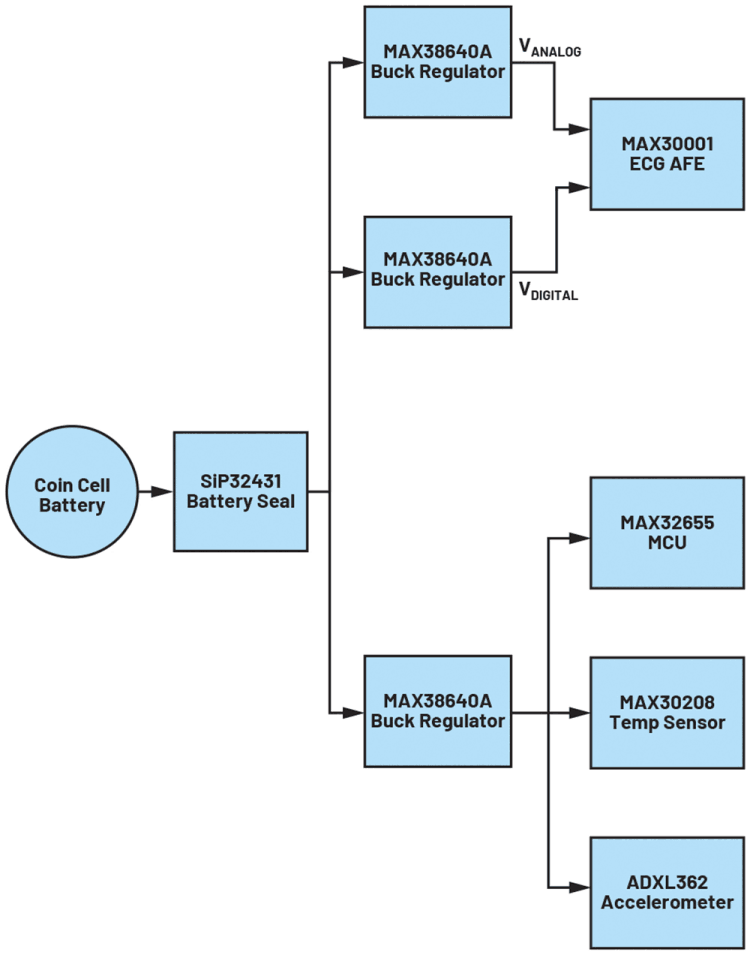
The patch shown in Figure 1 continuously monitors the ECG and accelerometer while checking the temperature every 15 minutes.
A 235 mAh CR2032 lithium coin cell battery provides power to the voltage regulators, microcontroller, ECG front end, temperature sensor and accelerometer. The data are transmitted via Bluetooth LE (BLE) once every two hours for a total of 12 BLE transactions per day. This patch incorporates three different modes, each with distinct load profiles: standard monitoring, temperature monitoring, and transmission modes. In standard monitoring mode, only the ECG and accelerometer are monitored. In temperature monitoring mode, an additional temperature sensor is monitored. In transmission mode, the BLE radio communicates the data while simultaneously monitoring the ECG and accelerometer data.
Power supply challenges
Designing an RPM, such as an ECG patch, poses multiple challenges for power supply designers. The design is typically space constrained and patches with several sensors may require multiple power rails. Because the RPM patch is usually intended to be a single-use item, a coin cell battery is typically the most cost-effective power source available to the designer. Using only a coin cell battery to supply power to the patch, a designer must be cognisant of the efficiency of the power supply subsystem.
An often-overlooked challenge for power supply designers is extending the shelf life of the product. Shutdown currents and battery self-discharge can shorten the life of any system. Therefore, it is important for a designer to determine if the RPM patch can meet operating time requirements after a typical shelf-life period and, if it cannot, what steps can be taken to preserve battery life before the patch reaches the end user.
Determining battery run time
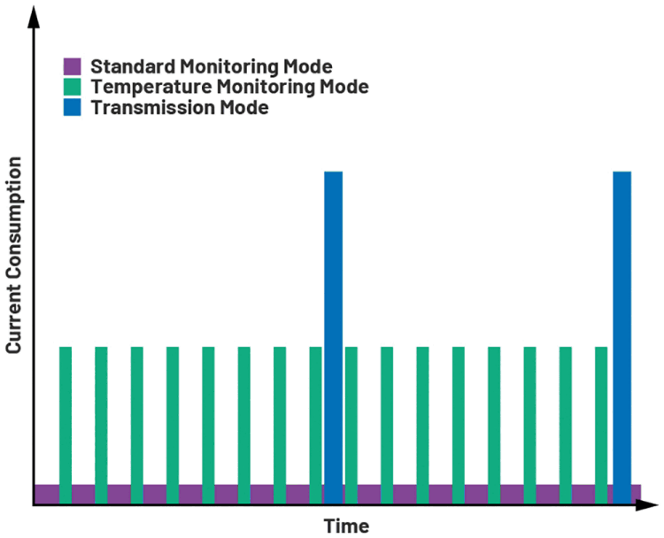
To accurately determine if the power supply solution meets battery life requirements, a load profile must be determined. A load profile is a simple representation of the load duty cycle of the system. For the remote patient monitoring patch we’re using, we’ll consider the three different operating modes that were previously presented: standard monitoring, temperature monitoring, and transmission modes.
In standard monitoring mode, the current consumption of the patch shown in Figure 1 (including the 330 nA quiescent current of each buck converter and the current draw of the MCU) is 1,88 mA. In temperature monitoring mode, the current draw is 1,95 mA for 200 ms every 15 minutes. In transmission mode, the current draw is 7,90 mA for 30 seconds every two hours while the patch is transmitting data via BLE. These values can be found within the respective device data sheets by looking at active and quiescent current specifications.
To start the load profile analysis, a duty cycle calculation is determined using the period for each operating mode during a day. Equation 1 is used:
which gives us the duty cycles for our patch seen in Table 1.
This gives rise to the load profile diagram shown in Figure 2.

Using this load profile we can calculate the current consumption of the patch. Taking the active current consumption of each operating mode, the average current consumption per day can be approximated from Equation 2:
A sample calculation is shown below:
Standard monitoring mode current per day = standard monitoring mode current × standard monitoring mode duty cycle × 24 hours
Standard monitoring mode current = 1,88 mA
Standard monitoring mode duty cycle = 0,9956
Therefore, standard monitoring mode current per day
Once each operating mode’s current consumption per day is found, the lifetime of the battery can be determined via Equation 3:
A sample calculation of battery lifetime period is shown below:
Battery capacity = 235 mAh
Standard monitoring mode current per day = 44,92 mAh/day
Temperature monitoring mode current
Transmission mode current
Therefore, battery life
The results of these calculations show that the device will meet the five-day runtime requirements with a battery life of over 5,1 days. This is deceiving, however, as this does not consider the shelf life of the system. In the medical device industry, it is best practice to design for a 14-month shelf life (12 months on the shelf, two months in transit).
Shelf-Life Considerations
Summing the shutdown currents of the devices in the system while using the typical 1 to 2% per year self-discharge rate of a CR2032 battery, one can see that, after 14 months, the battery does not have enough capacity to support a five-day runtime and a battery seal is required.
The battery capacity after 14 months on the shelf will be severely diminished as nearly 40% of the CR2032’s energy will be consumed by shutdown currents and battery self-leakage. Inserting this battery capacity into Equation 3, a more accurate run time can be determined:
Battery life (days) = 146,66 mAh/(standard monitoring mode + temperature monitoring mode + transmission mode)
Battery life (days) = 146,66 mAh/(44,92 mAh/day + 0,01 mAh/day + 0,79 mA/day) = 3,21 days
While sitting on a shelf for over a year, the battery capacity is impacted by battery self-discharge and system shutdown currents. Battery self-discharge is a function of the battery chemistry and environment. A CR2032 battery has a lithium manganese chemistry and a self-discharge rate of 1 to 2% a year. At the end of a year, the coin cell battery can lose 2% of its capacity while sitting dormant. Meanwhile, a BR2032 battery has a lithium carbon monofluoride chemistry and a self-discharge rate of 0.3% per year. It is easy to assume that the best battery chemistry for the application is the one with the lowest discharge rate but that is not necessarily the case. While the BR2032 battery has a lower discharge rate, it also has a lower capacity than a CR2032 battery cell with 200 mAh. By recalculating using the previous formulas, one can determine if such a lower capacity battery is adequate.
In this ECG patch, the IC shutdown currents are the greatest contributors to reducing battery life while the system is powered off. Shutdown current is drawn when an IC is disabled and there is no active load. These currents are usually due to leakage in the IC and ESD protection devices within the IC that draw small amounts of current even when there is no load. These currents are usually small (under 1 μA) but can have a massive impact on battery life. In this RPM patch, shutdown currents can reduce battery capacity by as much as 40% in a year. A battery seal can be used to limit the amount of current the system can draw from the battery while in shutdown.
Two common options for battery seals are mechanical battery seals in the form of a mylar pull tab and an electrical battery seal in the form of a load switch. Mylar/plastic pull tabs provide a mechanical battery seal where a plastic tab sits between the battery and the system. When the device is ready to be used, the user simply extracts the plastic tab and the battery begins powering the system. This is a simple, cheap, and proven mechanical battery seal that has been employed for many years. However, for medical devices, this solution is not always feasible. For an ECG patch where waterproofing is required, the slot from which the mylar protrudes can make the patch susceptible to water damage. In addition, the small plastic tab could potentially be difficult to use for an end user with low levels of dexterity.
A simple load switch, like the Vishay SiP32341, would make an excellent choice for an electrical battery seal. This device is an FET that, when open, blocks the battery from the rest of the system leaving the SiP32341 shutdown current as the only draw on the battery. The load switch has a logic control line that can be turned on via push button when the device is ready to be used. The SiP32341 has a 14 pA typical shutdown current, which is a dramatic improvement over the current draw of the entire system if no battery seal were in place. When the SiP32341 is used as a battery seal, a CR2032 primary cell retains 99,97% of its capacity over the course of 14 months. When no battery seal is used to protect the battery from the ECG patch shutdown currents, a CR2032 primary cell only retains 62,39% of its original charge. This 37% difference in capacity is what allows for the ECG patch to meet the five-day requirement after a 14-month shelf life.

A battery seal preserves battery capacity by preventing all the devices in the system from drawing shutdown currents from the battery. Over 99,9% of the battery capacity is remaining after the RPM patch sits idle for 14 months.
Inserting this battery capacity into Equation 3, a more accurate run time can be determined:
Battery life (days) = 230,25 mAh/(standard monitoring mode + temperature monitoring mode + transmission mode)
Battery life (days) = 230,25 mAh/(44,92 mAh/day + 0,01 mAh/day + 0,79 mA/day) = 5,04 days
Conclusion
The battery analysis of a system when it is active and when it is in shutdown/low power mode is critical to designing a power supply that will meet all the requirements for a medical device. While this article exclusively discussed an ECG patch that gathers heart rate, temperature, and acceleration data with BLE communication, the analysis and principles within this article can be applied to any number of medical device systems powered by a primary cell battery.
| Tel: | +27 11 923 9600 |
| Email: | [email protected] |
| www: | www.altronarrow.com |
| Articles: | More information and articles about Altron Arrow |
© Technews Publishing (Pty) Ltd | All Rights Reserved