Low temperature alloys have already allowed improvements in reworking high temperature SAC joints at lower temperatures. It is a different material set that process staff need to become familiar with but that does not mean it cannot be introduced into your process with existing process equipment.
Generally speaking, solders used in assembly reflow at over 220-230°C, however, the actual temperatures used are often 250-260°C. Low temperature solders, by contrast, can be reflowed at under 180°C. Organisations like iNEMI (International Electronics Manufacturing Initiative) are predicting a large growth in low temperature alloys in the next two to three years for multistep soldering. Most suppliers have all or most of the material set required for each soldering process.
HP, IBM Lenovo and others have been using LTS for a number of years on their products and have gained much practical experience. Many companies have been using tin/bismuth alloys for some years, reducing costs on PCBs and energy consumption. Other companies have been using tin/indium for rework of lead-free area array packages with success, specifically in an attempt to avoid damage to boards and other parts that can occur at high rework temperatures. There are savings to be made even if the indium solder alloy is much more expensive, provided you consider the total cost of manufacture. During rework only a small quantity of paste is used and in a rework centre the paste would last many weeks.
Considerable interest is also being shown in using robotics in soldering applications
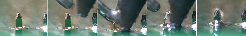 Figure 1. Slideshow illustrating the steps in automatic robotic soldering.
Soldering can be conducted with precision soldering irons or laser, but the fundamental rules of good soldering must still be followed to satisfy the most demanding applications for medical, industrial and automotive products. Precision soldering irons will be the dominant process combined with any use of LTS. The availability of cored wire still needs to be addressed, as do some of the issues with the ductility of the wire and possible ageing effects after manufacture.
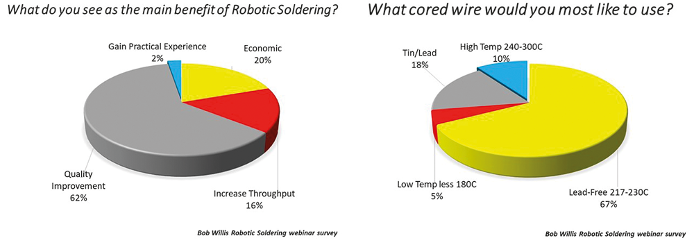 Figure 2. Survey results showing the growing use of robotic soldering.
Recent survey results from this presenter’s online events have shown that the driving force for robotic soldering is process and reliability improvements
What follows is the result of analysis focusing on LTS and robotic soldering to see the possible pitfalls.
BGA rework
BGA soldering with SAC balls and LTS is similar to the transition from a tin/lead to lead-free process. When BGAs were only available with SAC, the joints formed were a hybrid of the mixed alloys. When reflowing tin/lead paste, the SAC balls did not collapse but the tin/lead reflowed and formed joints through diffusion – the lead was only present in the base of the joint.
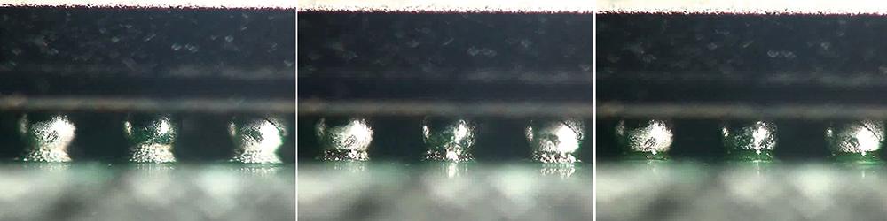 Figure 3. BGA solder joints forming with LTS (images taken from a video showing the rework process).
In the case of SAC and LTS, the process is visually similar but with reflow below 200°C leading to significantly less package warpage and high yields. It is important to control the volume of LTS paste to maintain the reliability of the joints. Reliability of the process has been demonstrated in many practical trials
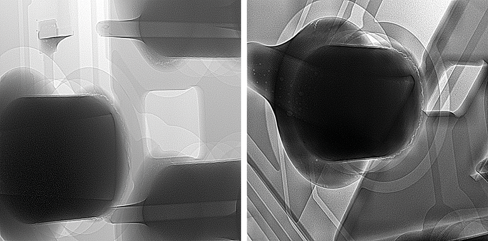
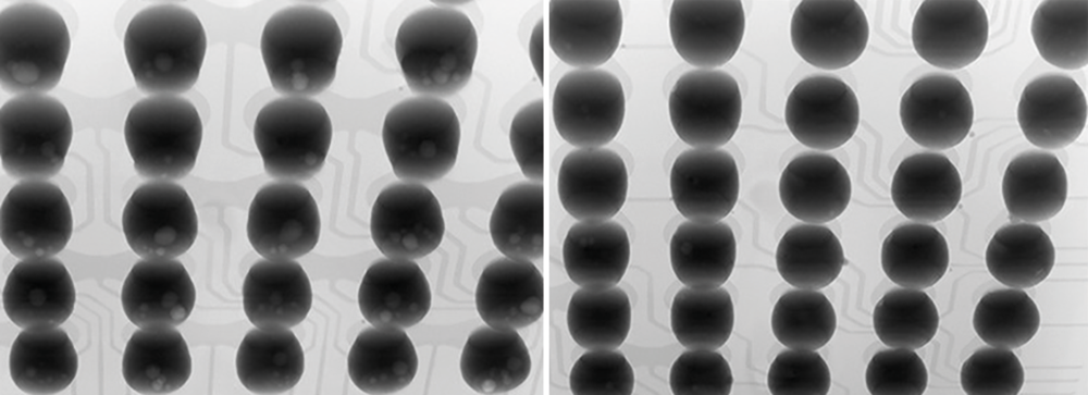 Figure 4. X-ray images after satisfactory low temperature rework with indium alloy.
Selective soldering
To understand the failure sites and to see how both optical and X-ray inspection could be used, sample boards assembled with LTS through a selective soldering system were subjected to thermal cycling. The selective process had a top-side preheat temperature of 90-100°C and a solder bath setpoint temperature of 255°C. The solder used was Sn64/Bi35/Ag1 with a melting point of 138°C. After thermal cycling, optical and X-ray inspection were used to see where joints may fail in the future.
As this small project was conducted during lockdown due to Covid-19, there were restrictions on what could be done in terms of testing. (It would have been ideal to conduct X-ray and microsectioning on samples before subjecting them to the second round of temperature cycling and also before the initial thermal cycling.)
In cases where the connector body separated from the pins, the connections were again subjected to pull strength measurement. In all cases the connector leads failed first, with no evidence of joint damage. The pull force was measured as being between
Experimentation has produced satisfactory through-hole joints using selective soldering equipment with a low temperature alloy on a four-layer, 1,6 mm thick PCB. The surface finish on the boards was nickel/gold and they had previously been through one reflow operation prior to selective through-hole soldering. The soldering quality easily met the requirements of
Optical inspection after 1000 thermal cycles between -55°C and +125°C showed no evidence of surface changes. However, after a further 1000 cycles, joints showed evidence of cracks in the surface of the solder. These were seen on the joint surface directly above the barrel of the plated through-hole and at the solder fillet interface on selected joints. There was no evidence of joint failure even at these temperatures. We have used even lower temperatures
The X-ray images in
We have conducted trials on reflow, wave, selective and robotic soldering with LTS with successful results. In addition, we have examined the differences in component and PCB surface finish solderability at lower temperatures. Many users have not examined hand soldering and rework for through-hole or surface-mount due to the lack of LTS wire. However, based on our trials we feel this can be implemented successfully in production.


© Technews Publishing (Pty) Ltd | All Rights Reserved
 printer friendly version