


The above title does not necessarily reflect a direct relationship between quality and hand soldering. It might be somewhat misleading. However, some 20 years ago, NASA and many military manufacturers all over the world would have sworn by hand soldering only. Why?
I remember around 1982 having to desperately search for hand soldering operators capable of producing top quality electronic circuitry and assemblies in KwaZulu-Natal. At first a carefully selected group was chosen from existing production lines assembling and soldering military boards by hand to meet the stringent criteria.
The paradigm of that era was based on the reliance of proven hand soldered quality products to MIL-STD- 2000 and MIL-STD-883 in particular for the hybrid thick film circuits manufactured in those days. MIL-STD-883 is still valid and used today while MIL-STD-2000 has been discarded to the benefit of IPC. In a previous article in the 23 July 2008 issue of Dataweek I explained briefly the recommended teaching/skill development criteria conversion between IPC-J-STD-001 and the now defunct MIL-2000.
Hand soldering, if well controlled and monitored, still remains the kindest way of treating both electronic components and printed circuit boards, as temperatures need not be as high as is generally seen in various manufacturing companies. IPC does not particularly recommend a 'good' temperature; in fact, looking at the latest IPC-J-STD-001D, appendix B under B-2 'Benchtop and hand soldering systems' mention is only made of the accuracy to maintain whatever temperature was chosen to within 5°C. Nothing is said about the actual temperature. Admittedly with the various solder alloys present today, not to speak of the lead-free variety, hand soldering operational temperatures are legion.
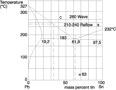
As an example, let us look at the most common solder prior to the lead-free invasion, namely the eutectic solder Sn63. Sn63 is an alloy composed of two metals, Tin (Sn) and Lead (Pb). Sn63 reflects the percentage of Tin, in this case 63%. The remainder must obviously be the Lead (Pb) or 36%. This alloy is one of many so called eutectic alloys.
Most of us will remember that a eutectic alloy has the property of moving from the solid state at room temperature to liquid when the temperature of the alloy is brought above the eutectic melting point in a very fast and swift way. The same holds when the molten alloy is cooling down to room temperature. After having reached 183°C, the molten solder swiftly turns solid again when cooling. It all happens very fast; this is a typical property of all similar eutectic solder alloys. There is no 'soft stage', so to speak.
Nowhere in IPC could I find the recommended lowest hand soldering temperature for this Sn63 eutectic alloy. TSI (Technical Services International – UK), once the owner of the famous school of soldering in Scotland is clearer in this aspect and recommends the following: Take the melting point of the solder and add 40°. In our example this means 183+40 or 223°C. So this is our lowest soldering temperature for eutectic Sn63.
Considering that a standard soldering operation to small components takes around 2 to 4 seconds, exposure and thermal shock are kept to a minimum.
Bulk soldering of assembled PCBs in a solder reflow oven for minutes at temperatures above 223°C cannot be anything other than detrimental to the overall quality of the solder joints and their reliability.
Wave soldering on the other hand is even worse. To compensate for the open solder bath and environmental thermal losses, temperature exposure for both PCB and components is even higher. Ramping up and cooling down cycles are also much shorter than with reflow, hence greater thermal shock and detrimental effect on reliability.
The binary phase diagram of eutectic Sn63 solder is given in Figure 1 with point A being the melting point, B the peak soldering temperatures during some reflow soldering operations and C the average wave soldering temperature of the wave hitting the PCB.
High temperatures and long processing times are not desirable for good strong solder joint formation. A popular approach to predict the effect of higher temperatures is to make use of the Arrhenius rate equation. This is an exponential law and depends on the activation energy of the solder and participating metals as well as on the temperature as can be derived from the formula where k is the rate constant, A is a pre-exponential factor, Ea is the activation energy, R is the gas constant and T is the temperature in Kelvin.
A general rule of thumb is that for every 10°C increase in temperature there is a doubling of the reaction rate. Thermal stresses, mismatches and cracks can be caused. What this boils down to is that the lower the temperature at which we solder, the better.
With the advent and promotion of lead-free solders the soldering temperatures generally increase. This makes the situation even worse. We can conclude that there is in fact a relationship between quality and hand soldering. Hand soldering beats reflow, wave and intrusive soldering hands down. Obviously from a manufacturing point though, it is slow and labour intensive.
Having demonstrated that hand soldering does in fact contribute to improved quality by the sheer fact that soldering takes places at lower temperatures and with shorter soldering times, takes us to the next step: total quality. Total quality has more to it. Quality also depends on materials, processes, environment and most of all: people.
Before we discuss the generalities of overall quality in electronic manufacturing let us go back to the soldering process and in particular look at the most popular solder used, the Sn63 alloy.
What is often not mentioned in many IPC courses is the fact that Sn63 is not such a wonderful alloy to solder with, be it soldering by hand or otherwise.
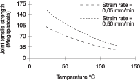
Temperature changes affect the tensile and shear strengths in tin/lead solders as is well known to those having had access to the 'mother of all standards' IPC HDBK-001. Tin/lead solders are more sensitive to this effect of stress than other alloys.
Strain rates of 0,2 mm/min have often resulted in failures after 1000 to 10000 temperature cycles. If your electronic product is sitting in cosy home or temperature controlled telephone exchanges, cycling is not much of an issue. However, for military, medical and space applications this is not the case.
Often sidestepped is the 'creep' of solder joints. Creep is a slow plastic deformation of the solder and carries on even long after the soldering process has ended.
Cyclic exposure of the solder joint to temperature, stress and strains will eventually result in further plastic deformations, leading to the formation of cracks. This effect can also be called 'fatigue'. In IPC HDBK-001, mention is made of the effect of fatigue. I quote: “The fatigue strength of the solder has a greater impact on the reliability of the connection than the static strength of the solder joint. The creep strength of the solder at operating temperatures can be as low as 1,4 MPa rather than the 34,5 MPa ultimate strength.”
Lower strain rates result in both lower solder joint tensile strength and shear strength. Lower strain rates offer more time for the solder to relieve stress and reduce the load on the solder joint. This can be seen in Figure 2, taken from IPC HDBK-001.
The static strength of the solder joint lies in the correct time/temperature profile, which is ideal and well controlled with hand soldering. This remark is obviously only valid for well and frequently trained soldering operators. Training is important.
Sufficiently long hexagonal copper/tin crystals are formed in a good and strong intermetallic bond. Soldering too long will result in de-wetting (crystals grow too long). The same is true when one solders at too high a temperature. Optimum crystal length for tin/lead solders lies between 1,5 and 2 micrometres. Anything shorter and we have bad wetting or even non-wetting. This can be seen in Figure 3.
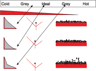
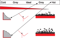
When soldering starts and the temperature time relation is not correct, there is not enough energy to let the intermetallic crystals grow to the correct length. Going further into the life cycle and soldering more often, or again, results in increased growth of those intermetallic crystals. The same happens when the temperature is set too high. Too long intermetallics result in a loss of tensile strength. Soldering once more increases the length of the crystals further, resulting in a collapse. This is called de-wetting and is THE END. One can not push back those crystals once fully grown. Neither further correction nor repairs to the PCB will cure this. Non-wetting in the beginning of the cycle can be rectified by either using the correct temperature and time with or without some aid of the proper flux.
There was previously a case where this lack of de-wetting knowledge and understanding cost a local company R400 000 over a single weekend. Just imagine how some of this money could have been used to train the staff!
This brings me to another element in the quality equation: people. Irrespective of the soldering method used by the manufacturer, people play a major role, if not the most important role.
Quality improvement has been high on the agenda of most successful companies globally for many years. Several methodologies and imaginative schemes have seen their ups and downs with various degrees of popularity over time. One that triggers the imagination and hints at involved statistics and mathematics is the six sigma method. Many protagonists stand by the six sigma method as being the most powerful method.
Six sigma is a disciplined and rigorous methodology using statistical analysis to measure and improve the company’s performance by correctly identifying defects or discrepancies. Defined metric methods are part of the process and here defects are measured in DPMOs or defects per million opportunities. To achieve six sigma, the manufacturing process must produce less than 3,4 defects per million opportunities.
Sub methodologies have made their appearance in time and some are known as LEAN, DMAIC and DFSS. (DMAIC stands for Define, Measure, Analyse, Improve and Control while DFSS stands for Design for Six Sigma). All of these rely on the willingness, capability and strength of the people involved in the quality process. Six sigma as a collection of metrics alone can not succeed without the support of top management and all stakeholders. The right tools and corporate commitment are tantamount to success, resulting in improved quality, cost reduction and satisfied customers.
Perhaps I could conclude here by quoting Peter Drucker: “Quality in a product or service is not what the supplier puts in. It is what the customer gets out and is willing to pay for.”
For more information contact Eddy van den Wijngaerd, +27 (0)21 712 5964, [email protected]


© Technews Publishing (Pty) Ltd | All Rights Reserved
 printer friendly version