


Infineon recommends the use of negative gate voltage to safely turn-off and block IGBT modules. In areas with nominal currents less than 100 A, the negative gate voltage is often omitted for cost reasons. The following paper describes special considerations for a unipolar drive of IGBT modules.
Turn-off to 0 V
The latest Infineon IGBT chip generations have several advantages. Some highlights especially, are a wider dynamic range, faster switching, less switching losses and lower conduction losses. When switching to 0 V, two effects may come into play:
* parasitic turn-on via the Miller capacitance;
* parasitic turn-on via stray inductances.
Turn-on via the Miller capacitance: When turning on the lower IGBT in a half-bridge, a voltage change dvCE/dt occurs across the upper IGBT/diode. This causes an approximate current:
to flow, which charges the parasitic capacitance CCG of the upper IGBT. The capacitances CCG and CGE form a capacitive voltage divider. Figure 1 depicts the current path via the Miller capacitance of the upper IGBT.
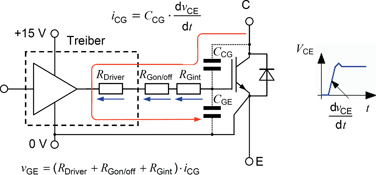
The current iCG flows via the Miller capacitance, the serial resistors, CGE and the DC-bus. If the voltage drop across the gate resistor exceeds the threshold voltage of the IGBT, a parasitic turn-on occurs. With rising chip temperature, the threshold voltage drops by several mV/K.
When the upper IGBT switches, a current flows via the Miller capacitance of the lower IGBT and may lead to parasitic turn-on here as well.
Turn-on via stray inductances: When turning off the load current a voltage:
is induced across the emitter stray inductance.
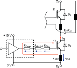
When switching the IGBT T1 on, the main current will commutate from the free-wheeling diode D1 to the IGBT. The diC2/dt produced from decay of the reverse recovery of the diode, induces a voltage on LσE2 and shifts the emitter potential of T2 to the negative. If the induced voltage produced through a high diC/dt is higher than the threshold voltage of the IGBT, this will result in a parasitic turn-on of T2.
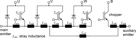
Parasitic turn-on in modules with common auxiliary emitter: In modules where the auxiliary emitter connections of several IGBTs are joined to a common emitter connection, very fast switching may result in an induced voltage across stray inductances of the emitter. The equivalent circuit diagram is depicted in Figure 3. The parasitic inductances in the module are here numbered Lσ1 to Lσ9. When turning on IGBT T2 an induced voltage across Lσ2 to Lσ3 results, which affects T2. The emitter potential of IGBT T2 is thus shifted resulting in parasitic turn-on of IGBT T2 when the voltage change exceeds the threshold voltage.
Proving parasitic switching
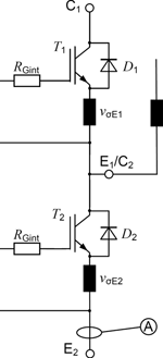
To prove parasitic turn-on, it is necessary to insert a current sensor in the bridge arm of the module (Figure 4). Two measurements may lead to the definite proof.
1. Double-pulsing the lower IGBT while blocking the upper IGBT with a negative voltage.
2. Double-pulsing the lower IGBT while the upper IGBT is shut off as done later in the application.
It is recommended to take two measurements with different currents between 0,1 X ICnom to 2 X ICnom.
Parasitic turn-on has been proven when the two current curves differ considerably. To be noted here especially is a higher current peak, a wider reverse current peak and/or an additional current pulse. Means to suppress the inadvertent turn-on are described later in 'Suggestions for Solutions'.
In applications with screw terminal power connections it is often possible to use a Rogowski coil for measurements. In most cases, however, it is not possible to measure directly in one arm. In smaller modules the load current is often brought to the PCB via solder pins. Here it is recommended one measures in the DC-bus eg, with a Rogowski coil or a shunt resistor.
Suggestions for solutions
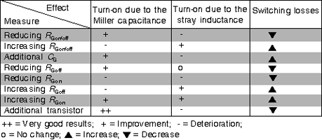
Variation of the gate resistor: The voltage change -dvCE/dt and the current change diC/dt during the turn-on process may be influenced by varying the gate resistor RGon. Increasing the gate resistor reduces the voltage and current changes. The IGBT switches slower; see Table 1. The capacitive parasitic turn-on may be obviated by reducing the RGoff value. The inductive parasitic turn-on, however, is prevented by increasing the RGoff value.
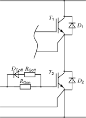
Separate gate resistors to achieve non-critical turn-on and turn-off: In many applications non-critical switching characteristics may be achieved when separate turn-on and turn-off resistors are used. Choosing RGoff < RGon (see Figure 5) prevents a capacitive turn-on via the Miller capacitance; (see paragraph 'Turn-on via the Miller capacitance'.)
Additional gate emitter capacitor to shunt the Miller current: The switching behaviour may be influenced with an additional capacitor CG between gate and emitter. The capacitor is to take up additional charge originating from the Miller capacitance. Due to the fact that the total input capacitance of the IGBT is CG||CGE, the gate charge necessary to reach the threshold voltage is increased (Figure 6).
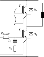
In applications where the IGBT module does not have an internal gate resistor it is recommended to place an additional resistor RS in series with the capacitor, to prevent oscillation. The recommended value for RS is:
RS ≈ 0,05 X RGon/off
These are values derived from experience.
The capacitance recommended for the additional capacitor is also derived from experience and is calculated by:
CG ≈/3 · V
Due to the additional capacitor, the required driver power is increased and the IGBT shows higher switching losses depending on how the RGon/off where modified.
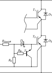
Transistor to shunt the Miller current (active Miller clamping): An additional measure to prevent the unwanted turn-on is shorting the gate to emitter path. This can be achieved by an additional transistor between gate and emitter (Figure 7). This 'switch' shorts the gate-emitter region after a time delay, as long as the driver shows a 0 V signal at its output. The occurring currents across the Miller capacitance are shunted by the transistor in a controlled manner. This guarantees safe switching.
Conclusion
Table 1 gives an overview of the measures discussed above with their advantages and disadvantages accordingly. RGon is used to turn the IGBT on; RGoff is used to block and to turn off the IGBT. RGon/off is the common resistor for turn-on and turn-off the IGBT.
For more information contact QD Power Components, +27 (0)11 466 2300.


© Technews Publishing (Pty) Ltd | All Rights Reserved
 printer friendly version