


The change from 63/37 eutectic to lead-free solder need not increase defects provided the new process is understood. This article examines the reflow process and the characteristics of different solders and fluxes, and their effects on common defects like solder slump, solder balling, solder bridging, wetting and dewetting, and voids.
Tin-silver-copper alloys are the primary choice for lead-free SMT assembly, although there are other options available, such as alloys containing bismuth or indium and other elements. However, tin-silver-copper solders, also known as SAC alloys, are by far the most popular, and are preferred by approximately 65% of users (Soldertec 2003).
The lead (Pb)-free SMT process differs from a 63/37 eutectic process in numerous ways. A good understanding of these differences when using SAC alloys, will enable process engineers to bring about the necessary changes to the SMT process to reduce soldering defects, increase lead-free assembly reliability, and maintain production yields.
Often when a manufacturer transitions to lead-free soldering an increase in defects is noticed. This is often a result of an improperly implemented process. A well-defined, optimised and controlled lead-free process will not augment defect rates. The main differences between a lead (Pb) and lead-free process are summarised below:
* Solder physical properties: melting point, surface tension, oxidation potential, metallurgy and metal leaching potential.
* Higher peak temperatures.
* Higher preheat temperatures.
* Lead-free finishes for boards and components (preferred).
* Solder cosmetics and surface effects.
* Solderability differences such as speed of wetting and spread.
* Less self-centring or alignment of components.
The liquidous temperature of SAC alloys is 217-220°C, which is about 34°C above the melting point of eutectic 63/37. This higher melting range requires peak temperatures to achieve wetting and wicking to be in the range of
235-245°C. Lower peak temperatures can be used with SAC solders such as
229°C. This lower peak temperature often can only be used for boards with lower overall thermal masses or assemblies, which do not have a large thermal mass differential across the board.
Higher reflow profile temperatures will require the use of newer solder paste flux chemistries. Solder paste flux accounts for nearly 50% of the solder paste volume. Its ingredients characterise the paste's rheological properties; its ability to print, avoid cold slump, tack life, stencil life and abandon time.
As the preheat is engaged during reflow, the flux system will prevent hot slump, prevent oxidation of the metals to be joined, deoxidise the solder powder and remove oxides of the metals to be joined. The flux system ensures an oxide free solder surface, and to give the lowest surface energies to enable spread and wicking of solder. After reflow is complete, the flux system must be easily removed in water, if it is a water washable paste, or remain benign if it is a no-clean type paste.
With some no-clean solder pastes the residue must not undergo complete polymerisation, thereby remaining pin-probeable. The basic ingredients in a solder paste flux can be summarised as below:
* Resins, solid and liquid types, activators, organic acid and/or hydrohalides.
* Solvents and co-solvents.
* Gelling agents.
* Surfactants.
* Chelating agents.
Solder paste manufacturers have had to revisit most of these ingredients to account for the higher temperatures experienced in Pb-free reflow operation. Most of these ingredients are organic compounds and thermal stability up to
245°C is essential to avoid issues of decomposition, oxidation, and polymerisation of paste flux during reflow.
Lead-free solder pastes designed for lead-free alloys, and also alloy specific, will function best and help prevent solder defects.
Typical defects associated with lead-free reflow soldering are: bridging; solder balls; mid-chip balling; poor wetting; voids; tomb-stoning; de-wetting.
Bridging, solder balls and mid-chip balling
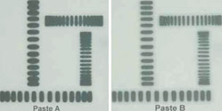
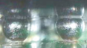
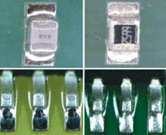
The first three defects: bridging, solder balls and mid-chip balling can arise from the solder selection process. Since preheats are higher with lead-free, the hot slump characteristics of the paste are critical; solder pastes with good hot slump at higher temperatures such as 185°C are needed. Traditional 63/37 pastes have already melted and flowed at these temperatures; the gelling materials have broken down. The example in Figure 1 demonstrates this quite well; two SAC solder pastes are shown. Both pastes were run through a reflow oven at 180°C. Paste B has better hot slump properties than Paste A and would be less likely to cause bridges, solder balls or mid-chip balling. For fine pitch components it is critical to select a lead-free paste with a heat stable gelling agent.
Poor wetting of terminations and pads
Non-wetting or insufficient wetting is also encountered. It must be understood that different metallisation will exhibit differing spread and wicking characteristics, and also flux activity will play an important role. Lead-free SAC alloys during solderability testing, using wetting balance instruments, demonstrated the best wetting when water-washable flux systems were used. No-clean flux systems containing less activator and/or free of halides demonstrated lower wetting speeds and lower maximum force readings.
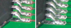
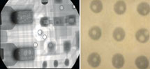
Bare copper OSP boards, which have seen more than one thermal cycle, are prone to incomplete pad wetting. While pure tin, silver immersion finishes exhibit better solder spread. Ni/Au, if the nickel is not affected with impurities or oxides, will normally also solder well. Figure 3 exhibits two examples: one with SAC alloy on copper and the other on silver immersion; both QFPs were reflowed in air, using a no-clean paste ROLO type flux.
Poor solderability, insufficient wetting, poor wicking of solder, and large contact angles can also result from an inadequate thermal profile. It is very important to achieve good thermal equilibrium across the whole board, and this becomes more important with lead-free since the peak temperature window is narrower. SAC alloys melts at 217°C while the peak temperature needs to be in the range of 235-240°C.
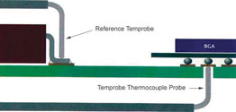
If BGAs are present on the lead-free assembly, because these components act as heatsinks, the solder paste may not completely reflow under the BGA, while other smaller components may show good soldering. It becomes very important to establish good thermal profiling points across the board, including under BGAs. To properly ensure wetting has occurred completely, optical inspection or X-ray inspection may be necessary.
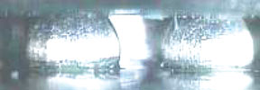
Figure 5 shows balls, which have not undergone reflow due to insufficient heat. By measuring the temperature accurately at the ball site, this can be avoided. The temperature at the ball site had not seen 217°C, the melting point of SAC balls. Figure 6 shows what happens when excessive temperature is seen by the BGA, in this case the temperature was measured at about 265°C at the ball site. Figure 7 shows the proper collapse of lead-free balls with the thermal profile properly set. The standoff distance may be higher with lead-free SAC due to its higher surface tension.
There are other reasons why lead-free reflow demonstrates poor wetting and the main causes are summarised below: solder paste activity level is too low; excessive preheat; too long a preheat; difficult to solder finishes; insufficient time above liquidus temperature; excessive oxidation of parts to be joined.
Lead-free solder pastes require activation to be sustained beyond traditional tin-lead systems up to 217°C and beyond for SAC alloys. Like traditional 63/37 no-clean pastes, such as ROLO types, the prevention of oxidation to parts and boards is critical. Flux classifications such as ROM1 may contain halides and are therefore better able to cope with oxides or difficult to solder parts.
Tin-silver-copper solders wet most metal surfaces more slowly, and adequate times above the melting point of the solder are needed to achieve good wicking and solder spread. Normally the range is 60-90 seconds with peak temperatures from 235-245° C. If soldering is jeopardised by oxidation, this can be verified using solderability test methods such as the wetting balance test.
Voids in lead-free joints and BGAs
Much has been written about void prevention when soldering with lead-free solder pastes containing tin-silver-copper. Excessive solder voids can create a reliability issue especially in applications where the lead-free assembly will be exposed to thermal cycling conditions or in applications where the assembly will be exposed to vibration, or flexing during box builds. Also voids can reduce thermal performance and reduce electrical integrity.
It must also be stated that smaller voids can, in some cases, increase reliability by changing the crack pattern. Studies have shown that there is no reduction in reliability when voids are present to up to 25% by volume in the joint. Voids can act as stress relievers, due in part to the compressive nature of air pockets.
This is documented in the technical paper, Voiding: Occurrence and Reliability Issues with Lead-free, by Martin Wickham of the National Physical Laboratory, UK.
Some causes of voids in joints are summarised below:
* Solder paste chemistry.
* Solder surface tension effects.
* Thermal profile.
* Oxidation of the outer surface of solder joints.
* Termination geometries, joint shape.
* Metallisation of finishes for boards and components.
* Component board out-gassing during reflow.
Lead-free alloys such as SAC alloys have slightly higher surface tensions compared to 63/37. It is important to select a solder paste that has a flux chemistry designed for the higher preheats and peak temperatures. Choosing a solder paste, which does not contain resins and activators that do not decompose at these higher temperatures is the primary factor in void reduction. Good solder paste manufacturers are designing flux systems for lead-free alloys.
The voiding potential information is often available for use during the paste selection process. Optimising the reflow profile as to remove any volatiles, by extending the preheat times and increasing the time above liquidous, will also help in reducing void entrapment. Ensuring components and boards are free of moisture and plating contaminants will also help to reduce voids. It has been shown that copper OSP tends to produce slightly higher volume of voids when compared to Ni/Au and silver immersion.
In some cases joint geometries are contributors. Components such as leadless chip carries or large flat surfaces, perpendicular to the board, will prevent out-gassing during the soldering process; this resulting in void increases. Solder flux by-products such as both liquid and gasses will have to slowly make their way upwards.
Tombstoning defects with lead-free
Lead-free may increase the uplifting of smaller components. This is due in part to the reduced wetting behaviour of lead-free alloys. Component placement is more important with lead-free alloys since less centring will occur. This can increase the incidence of tombstones.
SAC305 also tends to reduce tombstones, this alloy has a concentration of 96,5 Tin, 3,0 Silver and 0,5 Copper and has melting range of 217-220°C. Because of the small pasty range, the component prone to tombstone is tacked by the initial melting phase of the alloy.
A solder paste, which exhibits excessive out-gassing during the initial stages of the melting of the solder powder, will also increase tombstone defects.
De-wetting with lead-free
De-wetting is often due to a lack of flux activity. This behaviour rarely occurs with water-washable type pastes, since these pastes are highly activated. Lower activity solder pastes in the category of ROLO, halide free no-clean pastes tend to create this on more difficult finishes, such as bare copper OSP or on Ni-Au, where the nickel base metal may have experienced oxidation or plating contamination.
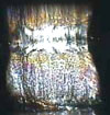
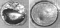
Figure 9 shows test coupons on which SAC no-clean paste was applied to two surfaces. The test coupons were then reflowed in air using the manufacturer's recommended thermal profile. The one on the left shows de-wetting while the one on the right exhibits good wetting. The pooling of the solder was due to the base metal being difficult to solder to. The molten solder initially spread across the surface, but not a good enough intermetallic bond was formed, resulting in surface tension pulling the solder away.
Ways to reduce or prevent de-wetting with lead-free SMT are: select a paste with excellent activity up to the melting point of the alloy, 217°C for SAC alloys; use a more active solder; ensure metals to be joined are oxide-free as possible; ensure base metals are solderable with the selected flux type; reduce the preheat time or temperatures as to preserve flux activity; increase time above liquidous
(217°C), if flux activity is good.
Excessive dullness and surface effects with lead-free
SAC alloys offer solder joints which are less reflective than 63/37; the contact angles tend to also be higher and spread is less. These are not considered to be defects but only cosmetic. If air reflow is used, SAC alloys will be less bright and show surface effects such as crazing, which are due to the intermetallics within the solder and oxidation effects. If nitrogen reflow is used, the joints will be more reflective and spread will be enhanced. Lower peak temperatures and times above liquidous will reduce intermetallic growth, and also increase the overall brightness of the solder joints.
Proper training will be required when transitioning to lead-free assembly. Operators will need to be given quality acceptance criteria for solder joints that will look quite different from traditional leaded systems.
| Tel: | +27 11 704 3020 |
| Fax: | 086 555 0111 |
| Email: | [email protected] |
| www: | www.ama-sa.co.za |
| Articles: | More information and articles about Allan McKinnon & Associates |


© Technews Publishing (Pty) Ltd | All Rights Reserved
 printer friendly version