
Ref: z263145m
Li-Ion rechargeable batteries are finding their way into many applications due to their size, weight and energy storage advantages. These batteries are already considered the preferred battery in portable computer applications, displacing NiMH and NiCad batteries, and cellphones are quickly becoming the second major marketplace for Li-Ion. The reason is clear. Li-Ion batteries offer many advantages to the end consumer.
In portable computers, Li-Ion battery packs offer longer run times over NiCad and NiMH packs for the same form factor and size, while reducing weight. The same advantages are true for cellular phones. A phone can be made smaller and lighter using Li-Ion batteries without sacrificing run time. As Li-Ion battery costs come down, even more applications will switch to this lighter and smaller technology.
Market trends show a continual growth in all rechargeable battery types as consumers continue to demand the convenience of portability. Market data for 1997 shows that approximately 200 million cells of Li-Ion will be shipped, compared to 600 million cells of NiMH. However, it is important to note that three cells of NiMH are equivalent to one Li-Ion cell when packaged into a battery pack. Thus, the actual volume is very close to the same for both.
1997 also marked the first year Li-Ion was the battery type used in the majority of portable computers, displacing NiMH for the top spot. Data for the cellular market showed a shift to Li-Ion in the majority of phones sold in 1997 in Europe and Japan. Li-Ion batteries are an exciting battery technology that must be watched. To make sense of these new batteries, this design guide explains the fundamentals, the charging requirements and the circuits to meet these requirements.
Li-Ion battery chemistry
Fully understanding a Li-Ion battery requires a little chemistry. Metallic lithium was first used in a few specialised rechargeable batteries, but it is extremely reactive. It actually burns and generates high levels of heat when placed in water. Because of this, it was never practical for a consumer-based battery. However, it was recognised as having excellent electrochemical properties for rechargeable batteries.
The development of Lithium-Ion (Li-Ion)-based batteries retained the beneficial electrochemical properties of metallic lithium without exhibiting most of the safety drawbacks. However, care must still be taken to not overcharge a Li-Ion battery. Overcharging results in the formation of pure lithium metal, which can react and cause overheating, fire and even explosions in extreme cases. Most Li-Ion batteries have built in safety mechanisms such as pressure-actuated electrical disconnect to prevent the most drastic consequences, but careful circuit design must still be done to ensure that the battery is not overcharged. At the very least, the battery will be damaged and have a shorter lifetime.
Figure 1 shows a chemical model of a Li-Ion cell. It consists of an aluminium cathode coated with a lithium-based compound. The anode is made of copper, coated with either carbon or graphite. The choice of the specific material does affect the electrical properties of the battery. For example, one of three lithium-based compounds is typically used. By far the most common is LiCoO2, which is a safe, high-capacity compound. LiNiO2 is less expensive and has high capacity, but it tends to be less safe. Finally, LiMn2O4 is the lowest cost alternative but at the expense of reduced capacity. All three compounds are found in various Li-Ion batteries, so do not be confused when different materials are quoted by the manufacturers.
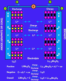
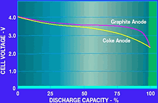
The choice of the anode material affects two major properties of the battery: the end-of-charge voltage and the internal resistance. A graphite anode has lower resistance and a higher end-of-charge voltage of 4,2 V. Carbon, on the other hand, has higher resistance and an end-of-charge voltage of 4,1 V. Check the battery specifications for the particular end-of-charge voltage. In either case, the battery must not be overcharged by more than 1% above the rating. The discharge profile of the two types of batteries is shown in Figure 2. Notice that the graphite battery has a flatter discharge slope than the coke battery. This is due to the lower internal impedance of the battery. Typically, a Li-Ion battery is usable from its maximum charge voltage of 4,1 V or 4,2 V down to a minimum discharge voltage of approximately 2,5 V. Again, check with the battery manufacturer for the recommended operating range.
Comparison to NiMH and NiCad
Which rechargeable battery to use is often a choice between NiCad, NiMH and Li-Ion. Figure 3 shows a table that compares the three battery types based on their capacity, lifetime and cost. Notice that Li-Ion batteries have a higher energy density per volume and weight. This means that a portable computer or cellular phone with a Li-Ion battery can be made smaller and lighter than the same design with a NiCad or NiMH. An alternative is to make the equipment with the same weight and size but with a significantly longer operating time per charge. For these reasons Li-Ion is quickly becoming the most popular choice for cellular phones and portable computers, even if the cost is higher.
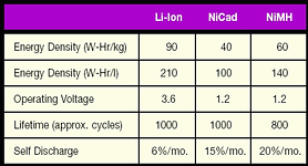
Li-Ion also has a low self-discharge rate, which means that the battery will retain its charge while sitting idle. The self-discharge for NiCad or NiMH is two and a half times to over three times greater than Li-Ion. Furthermore, Li-Ion does not exhibit the memory effect found in some NiCad batteries. Lastly, NiCad has environmental concerns regarding its disposal because of the cadmium.
There are some applications where the properties of NiCad are still needed. The most popular of these is power tools. In this case, the low impedance of NiCad batteries is needed for the high power surges. A Li-Ion battery's internal impedance means that high currents cannot be delivered efficiently.
Li-Ion charging
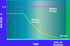
Figure 4a shows the charging voltage and current profiles for a Li-Ion battery. When a discharged battery is placed into the charger, the battery voltage is low and the charger is in a constant current mode. In other words, the charger circuit controls the charge current to a preset level. As the battery voltage increases during charging, it eventually reaches its end-of-charge voltage (4,2 V in this case). At this point, the current begins to taper off. Now the charger is in constant voltage mode, controlling the battery voltage to 4,2 V. The current continues to taper off, until it essentially reaches zero. Typically, Li-Ion charging is terminated after the current falls below a reasonably low level, such as 80 mA. An additional 30 to 60 minutes of low current charging may be used optionally to top off the battery.
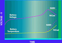
It is worthwhile to compare this charge curve with that of NiCad and NiMH batteries. Their characteristics for fast charge are shown in Figure 4b. For these two batteries, the charge current is set to a programmed level and the battery voltage and temperature are monitored. In the case of NiCad, the most common charge termination scheme is called '-ΔV/Δt'. The charger circuitry monitors the battery voltage and looks for the point at which it begins to decrease. At this point the charger switches to a trickle mode and reduces the current by 90%. For NiMH, the temperature is monitored and the charge terminated based on 'ΔT/Δt'. NiMH also has a decrease in battery voltage, but the magnitude is much smaller than NiCad, so it is difficult to detect. However, the temperature increase is large enough to detect and terminate the charge. Like NiCad, a NiMH battery is placed into trickle charge mode at approximately 10% of the full charge current.
Both of the charge termination schemes for NiCad and NiMH actually require a fair amount of circuitry. In both cases microcontroller functionality needs to be combined with an analog-to-digital converter and a temperature sensor to monitor the temperature and voltage. The microcontroller needs to compare readings to detect when either the voltage decreases or the temperature starts to rise quickly. Finally, the microcontroller needs to control the charge current to set it in full charge or trickle charge mode.
In contrast, charging a Li-Ion battery is actually a fairly straightforward process of voltage limiting, assuming that the precision requirements are met. When charging a Li-Ion battery, the most critical parameter is the end-of-charge voltage. Most battery manufacturers require a 51% tolerance around the end-of-charge voltage of either 4,1 V per cell or 4,2 V per cell. However, other parameters are important as well. For example, the minimum charge voltage is typically 2,5 V. Before a battery is charged, its voltage should be checked to determine if it is in the acceptable charge range, 2,5 V < VBAT < 4,2 V, for example. Again, check with the battery manufacturer for recommended charging ranges.
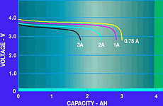
Battery capacity, expressed as C, is given in Amp-hours or mA-hours. It is used to estimate the total operating time of the battery given a certain operating current. For example, a typical Li-Ion battery is rated as 1600 mAh. If the battery is operated at 400 mA, it should operate for four hours. Unfortunately, it is never possible to realise the entire capacity of the battery due to internal losses. The graph in Figure 5 shows the effect of the operating current on the battery capacity. Higher currents result in dramatically-reduced operating capacity, primarily due to the internal impedance. This graph further illustrates why Li-Ion batteries are not appropriate for high current applications such as power tools.
During charging the recommended charge current is often expressed as C-rate. The C-rate measures how much current would be needed to fully charge the battery within one hour, assuming no losses. Of course, losses are present that do slow down the total charge time. For a 1600 mAh battery, the C-rate is 1600 mA. Manufacturers often specify the recommended charge current as a function of C-rate. In other words, a 1 C charge current equals 1600 mA. A 0,1 C charge current equals 160 mA. Check the C-rate specification for the recommended charge current of the battery you are using.
What about a 'battery pack?'
So far we have concentrated on a single cell Li-Ion battery. However, many batteries have multiple cells, which are combined into a battery pack. The pack usually includes some form of in-pack electronics. The main function of the in-pack electronics is to protect the pack from overcharging. For example, if a poorly rated external charger is used with a Li-Ion battery, the pack protection circuitry will monitor the charge voltage. If the voltage exceeds 4,2 V per cell, the pack protection will disconnect the battery, usually with two internal MOSFETs. For more robust operation, the in-pack circuitry should monitor each cell. For example, if three cells are stacked serially, the overall pack charge voltage is 12,6 V. Inside the pack, however, each cell still has a 4,2 V limit. Thus, the in-pack electronics should disconnect the battery in the case of overcharge of any one of the three cells.
The in-pack electronics usually contain an over-discharge monitoring circuit to disconnect the battery when the cell voltages drop below 2,5 V. Additional circuitry could include short circuit protection and temperature detection to prevent battery charging at temperatures above 60°C or below 0°C. More sophisticated circuitry may also include cell balancing and gas gauge functionality.
Even with built-in pack protection, the charger needs to be accurate. Since the consequences of overcharging a Li-Ion battery are drastic, the redundancy of an accurate charger and accurate in-pack protection is desirable.
Battery charging solutions
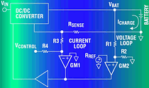
The main criterion in designing an Li-Ion battery charger is the accuracy. Three different solutions from Analog Devices make the job of designing an accurate charger easy. These are the ADP3801/02, the ADP3810/11 and the ADP3820 Li-Ion battery chargers. While the specific details and features of each product family are different, they all offer high accuracy in a system-level specification that takes the guesswork out of designing an accurate charger from discrete components.
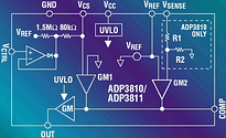
The ADP3801/02 uses a switching regulator topology for high efficiency and offers ±0,75% battery voltage accuracy. The parts also include valuable features such as an end-of-charge detector, a low dropout regulator, programmable final battery voltage and dual battery inputs. The ADP3810 integrates the analog control and sensing circuitry with a direct opto-coupler output, which makes it ideal for off-line applications. It offers ±1% final voltage accuracy in four different options: 4,2 V, 8,4 V, 12,6 V and 16,8 V. The ADP3820 rounds out the battery chargers with a linear charger controller. It offers the lowest part count solution where a linear charger is appropriate. Like the ADP3810, it offers ±1% final battery voltage accuracy.
What type of charger to use?
Once the battery type has been chosen, the next major question is which charger topology to use. This question needs to be answered regardless of the battery chosen, but the following discussion concentrates on Li-Ion. The topology choice depends upon the application and various system considerations. For example, an in-phone charger (placed inside a cellular phone) would probably need to be a switching regulator buck topology for the efficiency. A linear charger in the same application would dissipate too much power and generate too much heat. Thus, the efficiency of the charger may be more important because of the heat generated rather than the power lost.
In all chargers, there must be a power source. Typically it is an AC/DC adapter, often called a 'wall adapter' or a 'brick'. An exception to this is a charger for use in a car. This charger uses the car's 12 V d.c. The choice of how to partition the charger and the brick is illustrated for portable computers. Figure 6a shows the most common approach of having an external brick that provides a DC input to the computer and an internal charger circuit. Figure 6b moves the brick inside the computer and combines the charger with the brick. There are advantages to each approach. The external brick is typically an off-the-shelf item that does not require a separate design.
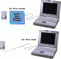
The internal brick saves the consumer from having to carry additional cords and the brick itself. Furthermore, combining the brick with the charger can save system cost. Essentially, the combination becomes an AC/DC supply with ±1% output voltage regulation and programmable output current. In the case of the external brick with an internal charger, the ADP3801/02 buck topology is ideal. On the other hand, the ADP3810 charger was designed primarily for AC/DC charger applications.
Another application is a cellular phone charger. Again, there are several different topologies: an in-phone charger, a desktop charger and a car adapter charger. In the case of the desktop charger, again the application can be divided into an external brick (wall adapter) or an internal brick/charger combination. Also, since the charger sits on a desktop, a linear charger such as the ADP3820 may be the best solution. However, an in-phone charger would probably require the efficiency of a buck solution such as the ADP3801/02.
Two key points will determine what type of charger to use. First, is the efficiency (due to heat generation) important for the application? If so, a switching-regulator-based charger is the best choice. If not, then a lower cost linear charger would be better. Second, what will the system topology or partition be? If there is a separate AC/DC brick, then a DC/DC charger (either linear or switching) is appropriate. However, the system cost may be lower if the brick function is combined with the charger function. In this case, an off-line charger application is the best. All three of these circuit approaches are detailed in the following sections.
A buck charger
The ADP3801 and ADP3802 are complete buck type switching regulator battery chargers/controllers. Figure 7 shows an application for a dual Li-Ion battery charger, pairing the ADP3801 with an external p-channel MOSFET. The 'BAT PRG MUX' allows one of six final battery voltages to be selected. These include one, two or three Li-Ion cells (4,2 V, 8,4 V and 12,6 V) and three intermediate voltages for NiCad or NiMH cells (4,5 V, 9,0 V and 13,5 V). Also, an input MUX allows the part to sequentially charge two independent battery packs, which could require different voltages.
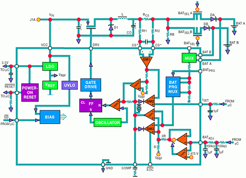
When a discharged battery is first placed in the charger, the battery voltage is well below the final charge voltage, so the current sense amplifier controls the charge loop in constant current mode. The charge current creates a voltage drop across the sense resistor RCS. This voltage drop is buffered and amplified by amplifier GM1. Amplifier GM2 compares the output of GM1 to an external voltage at ISET and servos the charger loop to make these voltages equal. Thus, the charge current is programmed using the ISET input. The output of GM2 controls the PWM duty cycle and the control loop. When the charge current is too high, the output of GM2 pulls the COMP node lower. It reduces the duty cycle of the PWM, decreases the charge current and provides negative feedback to complete the charge current control loop.
The output of GM2 is analog 'ORed' with the output of GM3, the voltage loop amplifier. As the battery voltage approaches its final voltage, GM3 comes into balance. As this occurs, the charge current decreases, unbalancing GM2, while control of the feedback loop naturally changes to GM3. To guarantee 50,75% accuracy, a low drift internal reference and high accuracy thin film resistors are used. Including these components on-chip saves the significant cost and design effort of adding them externally. After the battery has reached its final voltage, the current tapers off, as shown in Figure 4a. An internal comparator monitors the charge current and - when it drops below 80 mA - the EOC (end-of-charge) output pulls low. This signal can be used by the system to show that the battery has completed charging.
The LDO section of the chip provides a ±1% regulated output voltage for use either as a reference or as a supply voltage for external circuitry such as a microcontroller. The RESET pin gives a power-on reset signal if needed by a microcontroller. Finally, pulling the SD pin low places the ADP3801 in low current shutdown with only the LDO in operation. This can be very helpful in such cases as momentarily stopping charge (while a phone call is coming into a cellular phone) to prevent switching noise from interfering with the RF signal and to reduce the supply current when the charger is not needed. For more information on the ADP3801/02, consult the data sheet.
An off-line charger
The ADP3810 and ADP3811 are ideal for use in isolated chargers. Because the output stage can directly drive an opto-coupler, feedback of the control signal across an isolation barrier is a simple task. Figure 8 shows a simplified flyback battery charger.
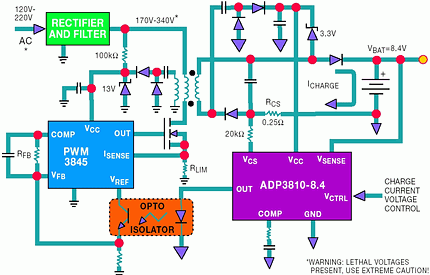
The primary side control IC is a standard current-mode flyback PWM controller. Its wide duty cycle range makes it a good choice for the universal 70-270 V a.c. operation and for the additional requirement of 0% to 100% output current control. This charger achieves these ranges while maintaining stable feedback loops. The PWM frequency is set to around 100 kHz as a reasonable compromise between inductive and capacitive component sizes, switching losses and cost.
The primary PWM-IC circuit derives its starting VCC through a 100 kΩ resistor directly from the rectified AC input. After start-up a conventional bootstrapped sourcing circuit from an auxiliary flyback winding would not work. The flyback voltage would be reduced below the minimum VCC level specified for the 3845 under a shorted or discharged battery condition. Therefore, a voltage doubler circuit provides the minimum required VCC for the IC across the specified AC voltage range, even with a shorted battery.
While the signal from the ADP3810/3811 controls the average charge current, the primary side should have a cycle-by-cycle limit of the switching current. This current limit has to be designed such that - with a failed or malfunctioning secondary circuit or opto-coupler or during start-up - the primary power circuit components (the FET and transformer) will not be over-stressed. As the secondary side VCC rises above 2,7 V during start-up, the ADP3810/3811 takes over and controls the average current. The primary side current limit is set by the 1,6 Ω current sense resistor connected between the power NMOS transistor and ground.
The current drive of the ADP3810/3811's output stage directly connects to the photo diode of an opto-coupler with no additional circuitry. With 5 mA of output current, the output stage can drive a variety of opto-couplers. An MOC8103 is shown as an example. The current of the photo transistor flows through the 3,3 kΩ feedback resistor, RFB, setting the voltage at the 3845's COMP pin and thus controlling the PWM duty cycle.
To minimise cost, a current-mode flyback converter topology is used. Only a single diode is needed for rectification (MURD320) and no filter inductor is required. A 1 µF capacitor filters the transformer current providing an average DC current to charge the battery. The resistor, RCS, senses the average current, which is programmed by a DC voltage on the VCS input pin. In this case, the charging current has high ripple due to the flyback architecture, so a lowpass filter on the current sense signal is needed. This filter has an extra inverted zero to improve the phase margin of the loop. The 1 µF capacitor is connected between VOUT and the 0,25 Ω sense resistor. To provide additional decoupling to ground, a 220 µF capacitor is also connected to VOUT. Output ripple voltage is not critical, so the output capacitor was selected for lowest cost instead of lowest ripple. Most of the ripple current is shunted by the parallel battery, if connected.
The VCC source to the ADP3810/3811 can come from a direct connection to the battery as long as the battery voltage remains below the specified 16 V operating range. If the battery voltage is less than 2,7 V (eg with a shorted battery or a battery discharged below its minimum voltage), the ADP3810/3811 will be in under-voltage lock out (UVLO) and will not drive the opto-coupler. In this condition the primary PWM circuit will run at its designed current limit. The VCC of the ADP3810/3811 can be boosted using the circuit shown. The ADP3810's VSENSE pin is connected directly to the battery. This allows direct sensing of the battery voltage for the highest accuracy. The internal precision trimmed resistor divider, the internal low drift reference and the internal low offset amplifier all combine to provide the ±1% guaranteed specification.
A linear charger
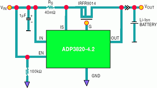
Figure 9 shows the ADP3820 linear Li-Ion battery charger controller. Its output directly drives the gate of an external P-channel MOSFET. As the circuit shows, a linear implementation of a battery charger is the simplest approach. In addition to the IC and the MOSFET, only an external sense resistor and input and output capacitors are required. The charge current is set by choosing the appropriate value of sense resistor, RS. As with the ADP380x and the ADP3810, the ADP3820 includes all the components needed to guarantee a system-level specification of ±1% final battery voltage. The ADP3820 has an internal precision reference, low offset amplifier and trimmed thin film resistor divider.
A universal charger
Many applications only require the charger to charge one specific battery. The form factor (physical dimensions) of the battery pack is usually unique to prevent the plugging in of other battery types. However, some applications require the charger to handle multiple battery types and chemistries. The design for these universal chargers is fairly complicated because the charger must first identify the type of battery, program the charge current and voltage and choose the proper charge termination scheme. Clearly, such a charger requires some sort of microcontroller intelligence. Figure 10 shows a simplified block diagram for a universal charger, using a microcontroller with the ADP3801.
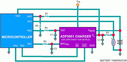
The microcontroller is used to monitor the battery voltage and temperature via its internal 8-bit ADC and multiplexer input. It also keeps track of the overall charge time. It may also monitor the ambient temperature via a thermistor or analog temp sensor. The ADP3801's LDO makes an ideal supply for the microcontroller, and the RESET pin generates the necessary power-on reset signal. The LDO can also be used as a ±1% reference.
When a battery is inserted into the charger, the first step is to identify the type of battery placed in the charger. The most common method of doing this is reading the value of the in-pack thermistor. Different values of thermistors are used to identify if the battery is Li-Ion or if it is NiCad/NiMH. This thermistor is also used to monitor the temperature of the battery. A resistor from the ADP3801's LDO to the battery's thermistor terminal forms a resistor divider and generates a voltage across the thermistor for the microcontroller to read. During this time, the ADP3801 should be in shutdown, which the µC controls via the SD pin.
When the battery has been identified, the microcontroller can do a prequalification of the battery to make sure its voltage and temperature are within the charging range. Assuming that the battery passes, the SD pin is taken high and the charging process begins. To program the charge voltage and charge current, two digital outputs from the µC can be used in PWM mode with an RC filter on the BAT PRG and ISET pins. A connection should also be made between the EOC pin of the ADP3801 and a digital input on the µC.
If the battery has been identified as NiCad/NiMH, the µC must monitor the voltage and temperature to look for -ΔV/Δt or ΔT/Δt criteria to charging. After this point has been reached, the charge current can be set to trickle charge. A timer function is needed to terminate charge if the charge time exceeds an upper limit. This is usually a sign that the battery is damaged and the normal termination methods will not work. The ADP3801's final battery voltage should be programmed to a higher voltage than the maximum expected charging voltage. Doing so prevents interference with the NiCad/NiMH charging yet still provides a limited output voltage in case the battery is removed. Meanwhile, the ADP3801 maintains a tightly regulated charge current.
If the battery has been identified as an Li-Ion battery, the ADP3801 is used to terminate charge. The µC should monitor the EOC pin for the charge completion signal. In some cases, the charge is continued for 30 to 60 minutes after EOC to top off the battery. If this is desired - upon receiving the EOC - the timer function should be started. After the allotted time, the ADP3801 should be placed in shutdown to prevent constant trickle charging. By using the high accuracy final battery voltage limit of the ADP3801, the circuit can guarantee safe Li-Ion charging without requiring an expensive reference and amplifier.
Conclusion
Li-Ion batteries offer exceptional advantages in run time, size and weight. These advantages are leading to the widespread use of Li-Ion in applications formerly served by NiCad and NiMH batteries. Trends show the Li-Ion is already the main battery choice for portable computers, and the same will be true for cellular phones in the near future. As production of Li-Ion increases and their costs reduce further, additional applications will switch to this battery type. Li-Ion charging does require high precision circuitry to guarantee safe and complete charging. Analog Devices offers a family of parts that satisfy the demands of Li-Ion while offering easy-to-use, cost-effective circuitry. These parts cover a variety of charger topologies, making the job of designing a Li-Ion battery charger easy.
Analog Data Products, 011 259 9400, [email protected]
© Technews Publishing (Pty) Ltd | All Rights Reserved